44 PMC-A
・After inserting the wire, check that it does not come
loose.
・Be sure the exposed section of the wire does not
touch the chassis or other wires such as the wire of
the adjacent terminal.
Connection and setup procedure
1.
Turn off the POWER switch and OUTPUT switch.
2.
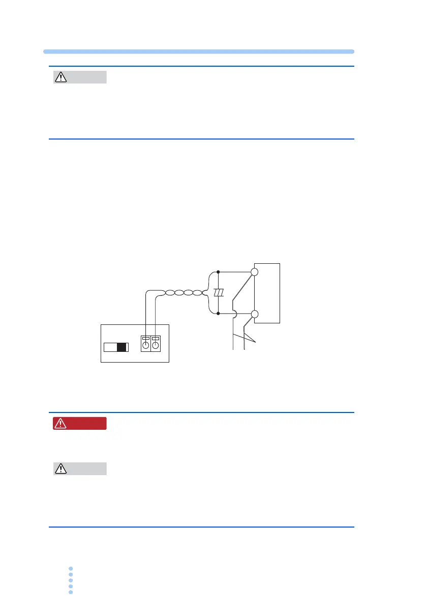
Connect the cables as shown in Fig. 4-3
For the handling of the SENSING terminal, see section Fig. 4-2
3.
Turn on the REMOTE SENSING switch.
Fig. 4-3 Connection of the sensing cable
・ For sensing cables, use cables with a higher
voltage rating than the isolation voltage of the
power supply.
・Burnout may occur in the load. If the sensing wires
come loose, the output voltage across the load can-
not be stabilized and may cause excessive voltage
to be applied to the load. Securely connect the
sensing wires such as by using crimp terminals.
REMOTE SENSING
OFF ON -S +S
+
+
Load
+S
Load cables
To OUTPUT
terminals
Twist
-S
W ARNING