68 PMC-A
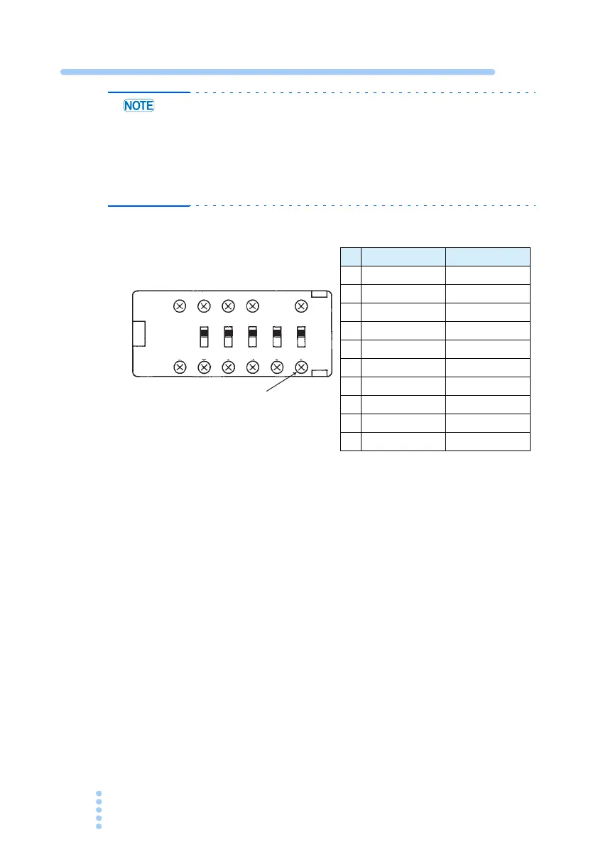
• Never touch variable resistor 6, because it is not to be
adjusted by the user. If you turn this variable resistor by
mistake, recalibration will be necessary. Please contact
your Kikusui agent or distributor.
• The functionality of the variable resistors is different
between Type I and Type II
Table 6-1 Variable resistors
Voltage system calibration procedure
The following four items are available in the voltage system.
Since the items are related, be sure to calibrate all items accord
-
ing to the following procedure.
• Output voltage offset
• Output voltage at full scale
• Voltmeter at full scale
• Preset voltage indicator at full scale
■ Connecting the equipment
1.
Turn off the OUTPUT and POWER switches.
2.
Connect the cables as shown in Fig. 6-2.
O.V.P
S1 S2 S3 S4 S5
1 2 3 4 5 6
A B C D
Do not touch this variable resistor
Type I Type II
A Vout MAX Vout MAX
B Iout MAX Iout MAX
C Vout OFS Not used
D Iout OFS Not used
1 V METER FS Not used
2 I METER FS V METER FS
3 I METER OFS Vout OFS
4 V LIMIT FS V LIMIT FS
5 I LIMIT FS I METER FS
6 Undisclosed Undisclosed
 Loading...