PMC-A 71
6
Maintenance
Current system calibration procedure
The following five items (two items on Type II models) are
available in the current system. Since the items are related, be
sure to calibrate all items according to the following procedure.
• Output current offset (Type I model only)
• Ammeter offset (Type I model only)
• Output current at full scale
• Ammeter at full scale
• Preset current indicator at full scale (Type I model only)
■ Connecting the equipment
1.
Turn off the OUTPUT and POWER switches.
2.
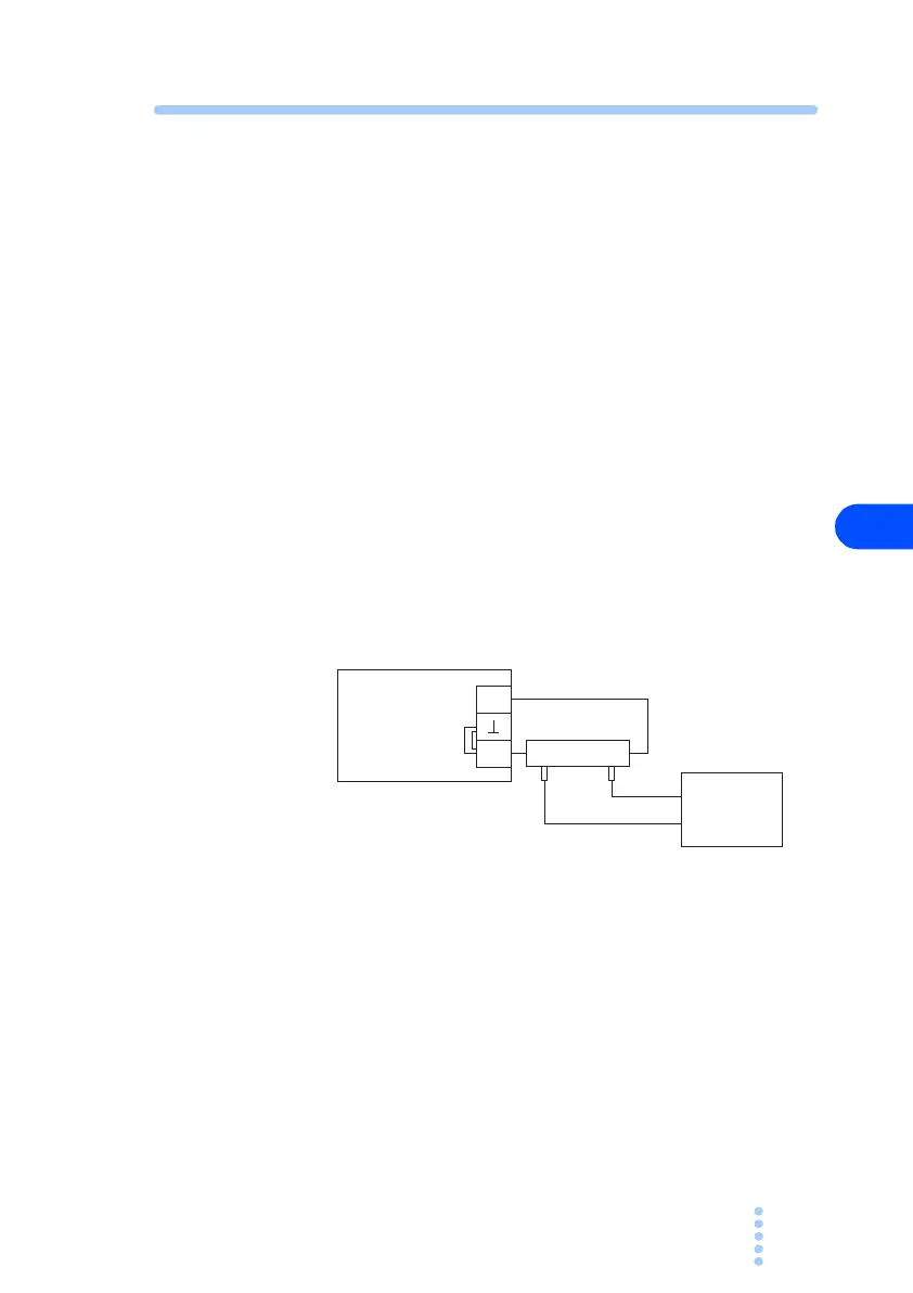
Connect the cables as shown in Fig. 6-3.
Connect the negative terminal and the chassis ground ter-
minal using a short bar.
Fig. 6-3 Connection for current system calibration
3.
Turn on the POWER switch.
■ Output current offset (Type I model only)
4.
Set the output current to 0 A.
When using local control, turn the CURRENT knob coun-
terclockwise all the way. When using analog remote con-
trol, set the control signal to 0 V or 0 Ω.
5.
Turn on the OUTPUT switch.
PMC-A
DC voltmeter
(DVM)
+
Shunt resistor
-