PMC-A 47
4
Basic Operation
■ Alarm
The alarm detected by single unit of the PMC-A can be also
detected under the master-slave parallel operation.
Connection and setup procedure
1.
Turn off the OUTPUT and POWER switches on all
power supplies that are to be connected in parallel.
2.
Choose the power supply that will be the master.
3.
Set the OVP (overvoltage protection) trip point on the
master and slave power supplies.
In parallel operation, set the OVP trip point not only on the mas-
ter power supply but also slave power supplies. However, set the
OVP trip point of the slave power supplies slightly higher than
that of the master power supply, so that the OVP function of the
master power supply is activated first.
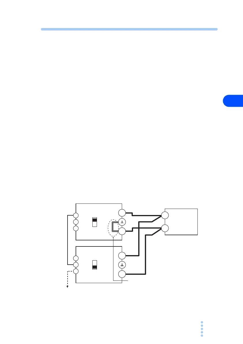
4.
Connect and set up each power supply as shown in Fig.
4-5. Set the S5 switch on all slave power supplies to
the down (0) position.
As for handling J1 terminal, see page 45, Fig. 4-4 Connection to
J1 terminal.
Fig. 4-5 Master-slave parallel connection and
setup
–
+
1
0
S5
2
3
1
J1
–
–
+
+
1
0
S5
2
3
1
J1
PMC-A master unit
PMC-A slave unit
To J1-2 of the next slave unit
Load
Connect the short bar to either the
negative or positive output terminal only
on the master unit
Up
Down
 Loading...