TOS5051A/5050A 6-23
Chap.6
Test Procedures
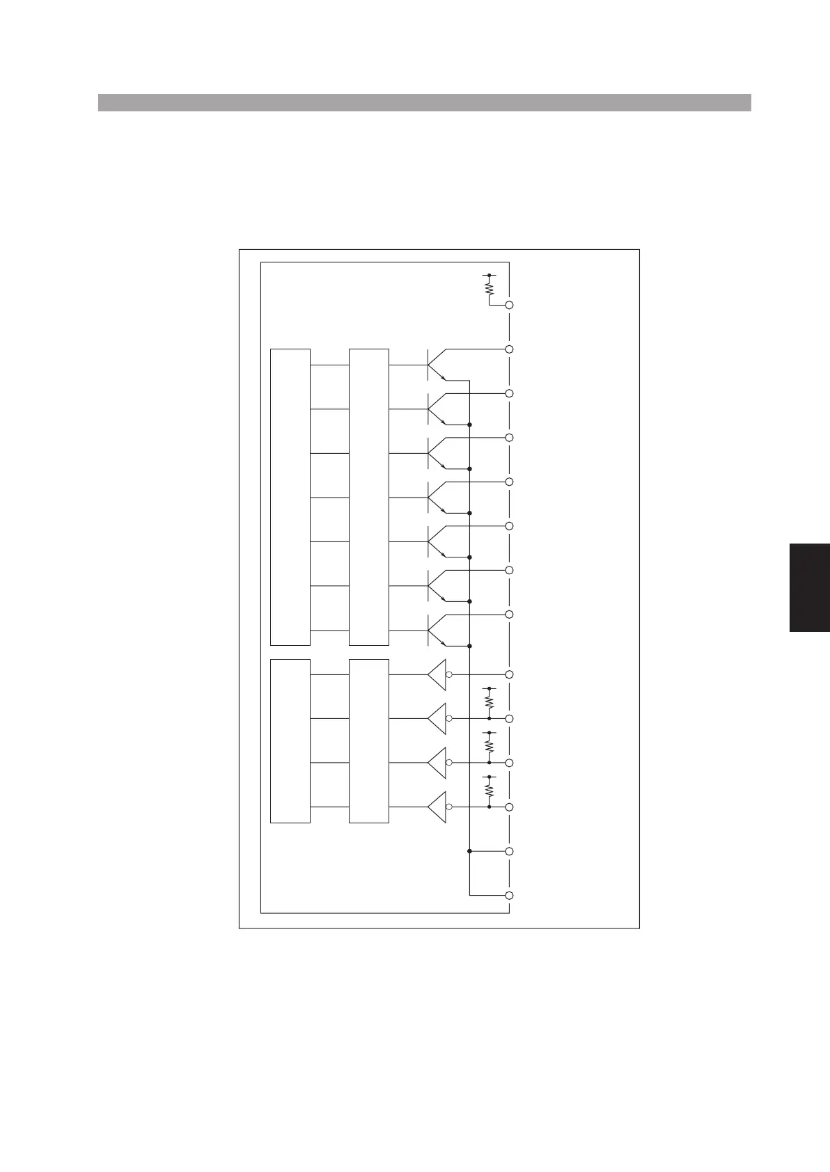
Internal construction
The signal output on the SIGNAL I/O connector is an open-collector output (see the
figure), and is isolated from the internal circuit by photocouplers. However, the cir-
cuit common is shared with the input signal.
Fig. 6-2 Internal construction of the SIGNAL I/O connector
1 INTERLOCK+
2 H. V ON
3 TEST
4 PASS
5 U FAIL
6 L FAIL
7 READY
8 PROTECTION
9 INTERLOCK-
10 RR START
11 RR STOP
12 RR ENABLE
13 ISOL COM
14 ISOL COM
Output signal controllerInput signal controller
PhotocouplersPhotocouplers