6. Analogue output management
6.a - Output diagnostics
With this function, you can check with a multimeter (or a regulator/display, or a PLC/BMS) if the transmitter outputs
are working properly. The transmitter generates a current (between 4 and 20mA) or a voltage (between 0 and 10V).
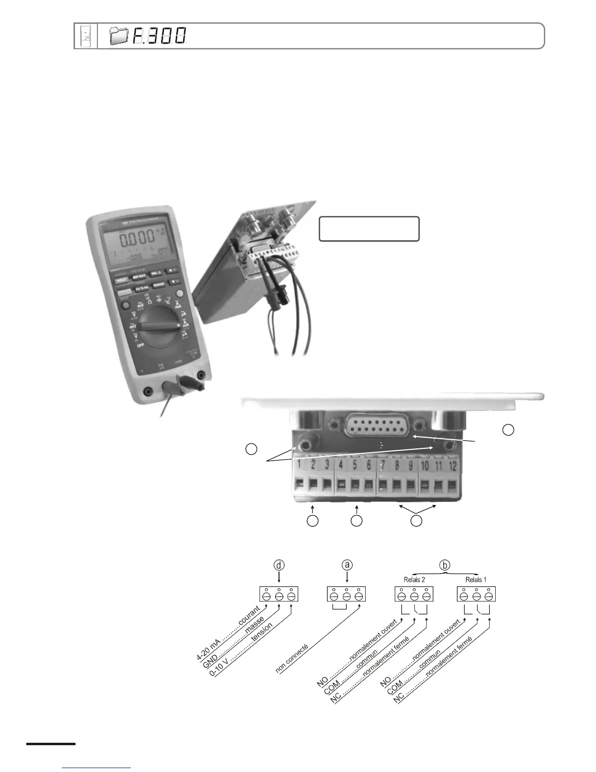
6.a.1 - Multimeter connection configuration
Before carrying out the output diagnostics, all connections and configurations of the transmitter must be
enabled, to avoid any damage on the transmitter and the multimeter !
Example of
connection
On the photo alongside, the multimeter is
connected to the 0-10 V output.
Page 8
Power supply
a
Analogue
output
d
Relays
terminal blocks
b
RS 232 connectors
LCC 300 software
e
Pressure
connection
c
CPE 300 transmitter configuration via remote control / Modbus