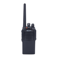
PTT Key
Press it to make a call and talk.
Programmable Key (Usually Alarm Key)
External Interface
Connect to an external earphone or
programming cable.
Channel Knob
Rotate it to select one from the channels
1 to 16.
2.2.Programmable Keys
To cater to users’ habits of operating the radio, programmable keys (i.e. side keys) are provided, which can
be configured as shortcut keys through programming by the dealer.
Note:
⚫Press: Press down and release quickly.
⚫Press and hold: Press down and hold still for a period, which is set through the CPS (customer
programming software).
The radio does not respond when this key is pressed.
Battery Level
Announcement
Announce the current battery level.
Switch to high/low power.
Initiate a broadcast call.
Switch to carrier squelch mode (i.e. cancel CTCSS) when the selected
analogue channel is CTCSS enabled. If carrier is matched, voice will
be output.
To go back to the previous state, press the key again.
Send an emergency alarm. It is used to seek help under emergency.