2.6 CONNECTING RODS
The connecting rods are made of nodular SG IRON,
fitted with split, white metal lined, precision steel
backed big end bearings and a push fit, bronze, small
end bearing bush. Internal oil ways permit oil to flow
from the big end bearing to the gudgeon pin bush, which
is adequately grooved for lubrication of the gudgeon
pin.
In case of 2 stage compressors, connecting rod with
needle roller bearing (on small end side) is used on high
pressure sides.
2.7 CRANKSHAFT
The crankshaft is accurately ground and dynamically
balanced, thus ensuring quiet operation good running
characteristics and high wear resistance. All bearing
Journals are precision machined to fine tolerances.
Internal oil ways feed oil to all main and big end
bearings (see fig. 6). The crankshaft rests on precision,
white metal lined walled bearings fitted in the crankcase
and bearing housing. In addition, in cases where
intermediate main bearings are fitted, these are of
similar construction as that of split big end bearing of
connecting rod. The bearing housing at the flywheel end
also incorporates the shaft seal which prevents the
passage of oil or refrigerant out of the crankcase.
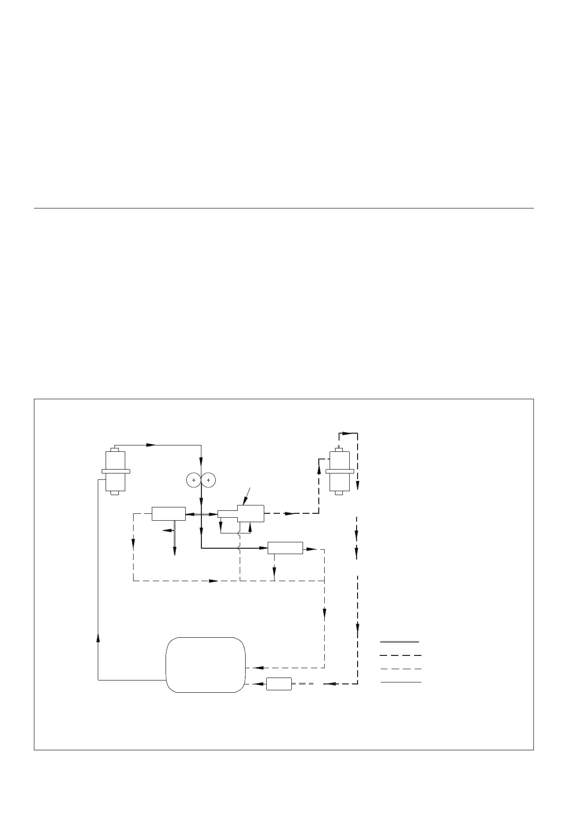
2.8 OIL PUMP
The compressor is fitted with a high pressure gear pump
provided with differential pressure regulator. In this way
a low pressure oil supply is made available for
lubrication purposes and a high pressure oil supply for
valve lifting mechanism. This high pressure oil supply
may also be used for capacity control, when installed.
The hydraulic time delay provides an interval of about ½
to 1 minute being the time necessary to enable the com-
pressor to start under "no-load" conditions. (see fig. 4)
The compressor is fitted with an adjustable oil pressure
regulator inserted in the oil return line. It is mounted
above the oil level glass, externally, on the crankcase.
. The regulator consists of a valve housing in which a
ball valve is held against the oil inlet by a spring. The
compression of this spring is adjusted by turning a set
pin, which is sealed by a nipple and washer, A cap.
which has to be removed before the oil pressure can be
adjusted, covers the nipple. After the cap has been
removed, the set pin can be turned with the aid of a screw
driver. To achieve a higher pressure, the set pin should
be turned in a clockwise direction. Within crankcase a
return line leads from the oil pressure regulator to the
level glass through which the oil jet can be observed,
(see fig. 5)
Figure 4 : Schematic Diagram of Oil Circuit
OIL PRESSURE REGULATOR
CRANKCASE
TO CAPACITY CONTROL
OIL PRESSURE GAUGE
CRANKSHAFT
SHAFT
SEAL
OVERFLOW RELIEF
VALVE
TO VALVE
LIFITING
DEVICES
HYDRAULIC
TIME DELAY
HIGH PRESSURE
OIL PUMP
OIL SUCTION STRAINER
OIL DELIVERY STRAINER
DIFFERENTIAL
PRESSURE
REGULATOR
CRANKCASE
HIGH PRESSURE
LOW PRESSURE
RETURN TO CRANKCASE
6
 Loading...