connection.
2. CONSTRUCTIONAL DETAILS
2.3 CYLINDER LINER
2.1 GENERAL
The renewable cylinder liners, made of fine grain cast
The compressor series KC comprises of 2, 3, 4, 6, 9, 12
iron centrifugally cast, are pressed into the cylinder
cylinders which are manufactured as single or two-stage
jackets and can be easily replaced. An extremely smooth
machines. These compressors are designed for
surface finish is obtained by precision boring and
Ammonia, Freon R134a refrigerants but can also be
honing. The collar at the top of the cylinder liner is
used for compression other gases. They are fitted with
provided with holes and serves as the valve seat for the
cylinders having a bore of 160 mm. The direction of
suction valve ring. The cylinders are numbered for ease
rotation is anticlockwise, while looking from the
of reference (e. g. in case of complaints, overhaul
flywheel end. Maximum safe delivery pressure for
2
reports etc.). Looking from the flywheel end, the
continuous operation is 20 kg/cm gauge. Minimum
numbering is from right to left and increases in the
speed is 450 rpm and the maximum 1000 rpm.
direction of the oil pump. Hence for a 6-cyl. compressor
2.2 CRANKCASE AND CYLINDER JACKETS
the first line of cylinders from flywheel end is numbered
from right to left, as 1,2 and 3. The second line from
Crankcase and cylinder jackets form a fabricated all
right to left is then numbered 4, 5 and 6.
welded, gas-tight steel structure, ensuring absolute
stiffness and mechanical strength, with a relatively low
2.4 VALVES
weight and a high impact strength. After welding, the
The suction and delivery valves are of ring type and of
complete unit is stress relieved and cleaned. The suction
special steel. Their design ensures ample gas passage
inlet to the compressor is through suction manifold in
with a minimum lift. The suction valve seat machined
which a removable strainer is fitted, thus ensuring that
on the upper face of the cylinder collar and the suction
the suction gas is filtered before entering the
valve ring is held into this seat by two sinusoidal springs
compressor. The suction manifold is connected to the
between the valve seat type collar of the cylinder liner
space between the cylinder liner and jacket. In this space
and a stroke limiter. This stroke limiter also locates the
any oil entrained in the gas is partially separated out and
delivery' valve seat and is centered by the collar of
is returned to the crankcase via a non-return valve. In the
cylinder liner.
H.P. cylinders of two-stage compressors, this non-return
valve is replaced by a plug, as the space round the H.P.
The three delivery valve rings with their valve springs
cylinder liner, being under intermediate pressure should
and the stroke limiter are assembled to the delivery
not be in connection with the crankcase where a lower
valve seat by means of a centre bolt with nut. This unit is
pressure (L. P. suction pressure) prevails. An open
held against the suction valve stroke limiter by a heavy
connection would cause a considerable reduction in
buffer spring. This construction enables delivery valve
compressor capacity.
seat as well as the stroke limiter to lift in case of liquid
stroke to avoid undue material stresses.
The cylinder heads are provided with cooling water
jacket fitted with inlets and outlets (3/4" BSP sockets).
2.5 PISTONS
Cooling is adopted if the compression temperature is
The light-alloy pistons are die cast and provided with
higher than 120°C. The cooling water should be non-
three piston rings and two scraper rings, one of the later
corrosive. The cooling water discharged from the
being positioned below the case hardened and ground
condenser should be used for cylinder cooling as the
steel gudgeon pin. Due to this an extremely good piston
water inlet temperature to the cylinder jacket must
seal is obtained, none the less providing adequate
exceed the condensation temperature of the refrigerant.
lubrication together with minimum oil consumption.
The manifolds are provided with pressure gauge
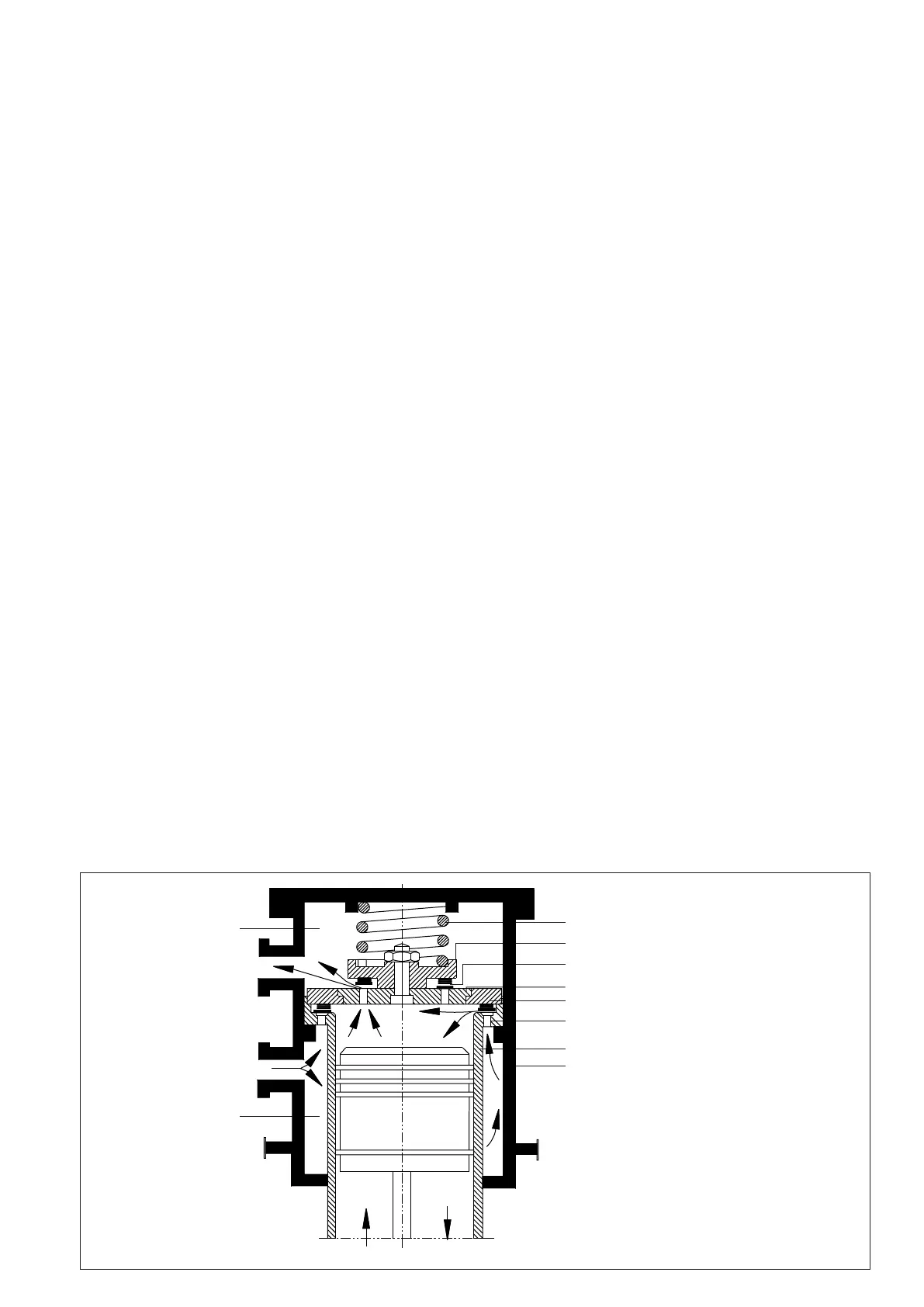
Figure 3 : Schematic Construction and operation of suction and discharge valve
1. Buffer Spring
2. Discharge Valve Stroke Limiter
3. Discharge Valve with Springs
4. Discharge Valve Seat
5. Suction Valve Stroke Limiter
6. Suction Valve Ring with Springs
7. Cylinder liner, also suction valve seat
8. Cylinder Jacket
1
2
3
4
5
6
7
8
DISCHARGE
CHAMBER
SUCTION
CHAMBER
5
 Loading...