33
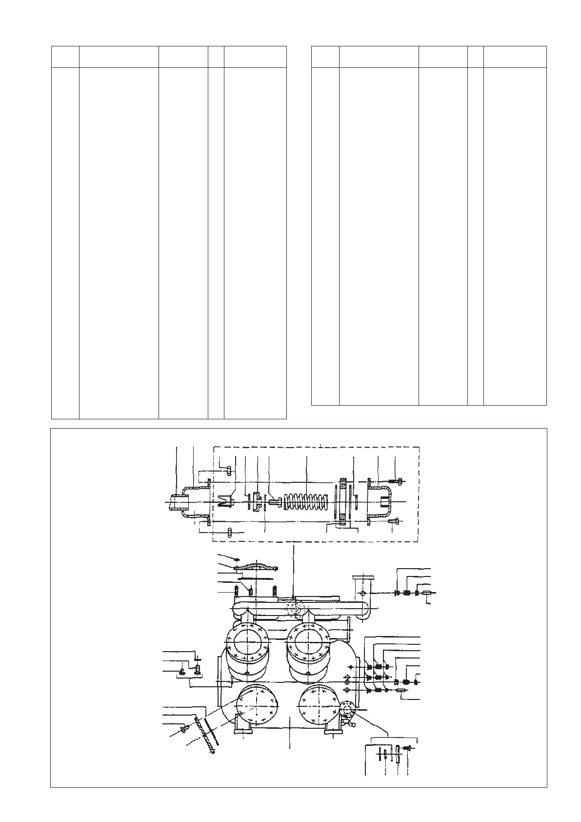
11.1 CRANKCASE ASSEMBLY WITH
SAFETY VALVE (FIGURES-31)
Sr. Name of the part Part no. Qty. Remark
No.
*1A Crankcase ass/v. 082.01.025.50 1 For KC2
*1B Crankcase ass/v. 083.01.025.50 1 For KC3
*1C Crankcase assly. 084.01.025.50 1 For KC4
1C Crankcase assly. 086.01.000.51 1 For KC6
1E Crankcase assly. 080.01.000.51 1 For KC9
1F Crankcase assly. 090.01.000.51 1 For KC12
1G Crankcase assly. 342.01.000.50 1 For KC21
*1H Crankcase assly. 343.01.025.50 1 For KC31
1I Crankcase assly. 344.01.000.50 1 For KC42
1J Crankcase assly. 345.01.000.50 1 for KC51
1K Crankcase assly. 346.01.000.50 1 For KC63
1L Crankcase assly. 347.01.000.50 1 For KC72
1M Crankcase assly. 330.01.000.50 1 For KC84
1N Crankcase assly. 348.01.000.50 1 For KC93
1O Crankcase assly. 349.01.000.50 1 For KC102
2A Cylinder Cover 082.28.100.50 - except KC4,31
(QTY. as per Cyl.)
2B Cylinder Cover 084.28.100.50 - For KC4,31
3A Gasket for Cyl. cover 082.28.650.50 - Except KC4,31
3B Gasket for Cyl. cover 084.28.740.50 - For KC4,31
4 Stud (Short) M 16 x 35 999.03.700.50 10 Per Cylinder
5 Stud (Long) M 16 x 65 999.03.710.50 2 Per Cylinder
6 Packing 999.18.525.50 - For HP Cyl
7 Blind Plug 1/4" BSP 999.30.950.50 - For HP Cyl
8 Non-return valve 082.06.000.50 - For LP Cyl
9 Gasket for side cover 993.00.311.00
10 Side Cover 082.28.110.52 -
11 Hex Hd screw M16x 35 999.01.690.50 8 per side cover
12 Gasket for sight glass 993.00.305.00 4
13 Oil Level Glass 082.28.170.50 2
14 Oil level glass cover 082.28.180.50 2
15 Hex Hd screw M8 x 30 999.01.624.50 12
16 Welding Nipple 082.01.520.50 1 For 22 dia tube
17 Welding Nipple 082.01.500.50 4 For 15 dia tube
18 Welding Nipple 082.01.522.50 2 For 6 dia tube
Sr. Name of the part Part no. Qty. Remark
No.
19 Ferrule 999.16.019.50 4 For 15 dia tube
20 Union Nut 999.16.079.50 4 For 15 dia tube
21 Ferrule 999.16.001.50 2 For 6 dia tube
22 Union Nut 999.16.063.50 2 For 6 dia tube
23 Cylindrical Pin - 6 dia 999.09.650.50 2
24 Cylindrical Pin - 15 dia 330.24.010.50 2
25 Pipe for seat - 1 Refer Sr. 26.
26 Bottom Housing Assly. 336.13.015.50 1 Welded to C' case
27A Set of safety valve parts 336.13.00 - Single stage & two
stage HP side
27B Set of safety valve parts 342.15.00 - Two stage LP side
27.1 Hex nut M8 999.06.623.50 6
27.2 Valve Guide 336.13.001.50 1
27.3 Ring Teflon 336.13.002.50 1
27.4 Cup spring 336.13.003.50 1
27.5 Hex Hd Screw M8 x 35 999.01.625.50 1
27.6 Spring 336.13.005.50 1
27.7 Ring adjusting 336.13.008.50 - Qty as per press
adjustment
27.8 Top Housing Assly. 336.13.009.50 1
27.9A Hex Hd Screw M8 x 50 999.01.628.50 2
27.10A Hex Hd Screw M8 x 35 999.01.625.50 4
27.11A Gasket 993.00.306.00 1 For Item 27 A only
27.9B Hex Hd Screw M8 x 50 999.01.628.50 2
27.10B Hex Hd Screw M8 x 35 999.01.625.50 4
27.11B Gasket 993.00.306.00 2 For Item 27B Only
27.12A Distance Ring -Not Reqd.- 1
27.12B Distance Ring 342.15.003.50 1
27.13 Safety Plate 351.03.105.50 1
28 Welding Nipple Dia 22 082.01.520.50 1
29 Ferrule Dia 22 999.16.027.50 1
30 Union Nut Dia 22 999.16.087.50 1
31 Hex Nut M16 999.06.687.50 16 per cylinder
* These crankcase assemblies are with integral suction housing.
25 26
27
27.1 27.2 27.3 27.4 27.5 27.6 27.6 27.6 27.6
27.13 27.12 27.11 27.10
31
2
3
4
5
17
19
20
23
17 OR 28
19 OR 29
20 OR 30
18
21
22
24
12 13 14 15
6
7
8
9
10
11
Figure 31
1
 Loading...