2.12 SAFETY VALVE
The compressor is fitted with one or more safety valves
depending on type of compressor. The safety valve is a spring-
loaded relief valve fitted between the delivery and suction
manifolds. At the time of excessive pressure in the delivery
manifold it by-passes gas back into the suction line. The
device can be easily removed for inspection or renewal.
The compressor should not be kept running with an open or
leaking safety valve as the machine would then become too
hot and the possibility of damage to, or even seizure of, the
piston and cylinder would arise. The line on the suction side of
the safety valve should be cold when the compressor is
operating. When it is found warm, the safety valve is leaking,
causing loss of capacity. In this case the safety valve must be
repaired or renewed.
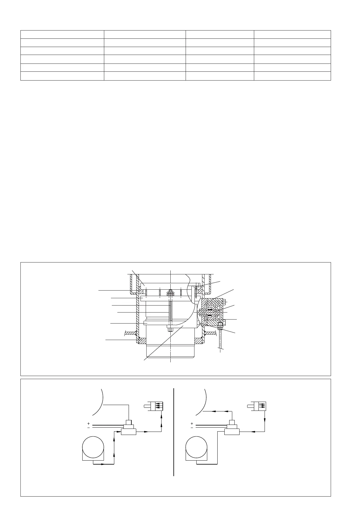
2.13 VALVE LIFTING MECHANISM -
Ref. Fig. 7 and 8
This mechanism can be subdivided into hydraulic and
mechanical components. The hydraulic assembly consists of
a piston housing with a teflon ring sealed piston controlled by
Figure 7 : Arrangement of Valve Lifting Mechanism
oil pressure. The mechanical assembly consists of a operating
ring to which are attached two actuating rods on its underside.
Eight valve lifting pins are located around the upper face of
the operating ring and the whole assembly is free to move in a
vertical direction.
The actuating rods pass through a supporting ring which is
rigidly held in a groove around the outside of the cylinder
liner. Pressure springs are fitted around each actuating rod,
tending to force the operating ring in an upward direction. To
the lower end of the actuating rods is attached a semicircular
lever, the fulcrum of which is fixed to the supporting ring. The
movement of this lever is controlled by the piston stem of the
hydraulic assembly bearing against its upper end.
In the "No-load" position the operating ring is in the upper
position, thus lifting the suction valve ring. When the
hydraulic piston is moved in towards the cylinder liner by the
high pressure oil it bears against the lever, causing the
actuating rods to be drawn down against the spring load. This
causes the valve lifting pins to be retracted thus enabling the
suction valve ring to descend on to its seat, thereby putting the
cylinder on load.
2.11 LUBRICATING CHART
Recommended Lubricants for Single Stage, Two Stage & Booster Compressors (ISO VG 68 Grade):
Sr. Brand Quality of Oil Suitable for Refrigerant Evaporation Temp. Range
01 Indian Oil (IOC) Servofriz-57/68 NH3, R12, R22 +10 to -25°C
02 Hindustan Petroleum (HP) SEETUL-68 NH3, R12, R22 +10 to -25°C
03 Bharat Petroleum (BP) Bharat Freezol-46/68 NH3, R12, 22 +10 to -25°C
04 Shell Clavus Oil-46/68 NH3, R12, R22 +10 to -25°C
05 Castrol Castrol Refrigeration Oil-46/68 NH3, R12, R22 +10 to -25°C
Note:
1. No two or more brands of oil to be mixed together for lubrication purposes.
2. Whenever you need to change brand of oil from earlier one, whole refrigeration system to be flushed with Nitrogen so that no traces of earlier oil exist in
refrigeration system.
3. When evaporating temperature is below (-)25°C suitable synthetic oil (ISO VG 68 grade) is to be used. (contact KPCL for details).
Figure 8 : Arrangement of Oil Control Piping for Loading-Unloading of Cylinders
UNLOADER PISTON ASSY.
(V L D PISTON ASSY)
COMPR.
CRANK
CASE
COMPR.
CRANK
CASE
UNLOADER PISTON ASSY.
(V L D PISTON ASSY)
220 V AC220 V AC
SOLENOID VALVE SOLENOID VALVE
1
3
2
1
3
2
OIL
PUMP
OIL
PUMP
SOLENOID VALVE ENERGIZED
COMPRESSOR CYLINDER ON LOAD
SOLENOID VALVE NON-ENERGIZED
COMPRESSOR CYLINDER UNLOADED
SUCTION VALVE RINGCYLINDER LINER
GASKET
PRESSING RING
TAP BOLT
ACTUATING ROD
PRESSURE SPRING
RING WITH
HINGED POINT
CRANKCASE
CYLINDER
VALVE LIFTING PIN
V L D PISTON
HOUSING
FULCRUM PIN
V L D PISTON ASSY.
OIL PASSAGE
SEMI CIRCULAR LEVER
FROM OIL DISTRIBUTOR OR
THREE WAY SOLENOID VALVE OR OIL PUMP
8
 Loading...