EasyManua.ls Logo

KitchenAid KBMS1454R - Component Access and Removal; Component Locations

KitchenAid KBMS1454R
68 pages
Print Icon
To Next Page IconTo Next Page
To Previous Page IconTo Previous Page
Loading...
4-1
COMPONENT LOCATIONS
This section instructs you on how to service each component inside the Built-In Microwave Oven.
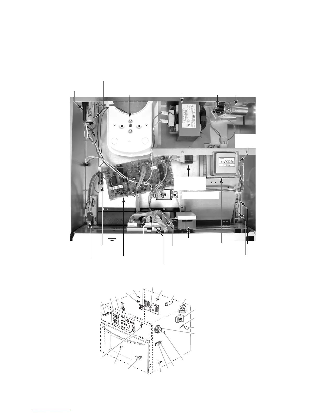
The components and their locations are shown below.
COMPONENT ACCESS
Power Supply Cord
Line Filter Capacitor
Cooling Fan Motor
High Voltage
Transformer
High Voltage Diode
& Capacitor
Secondary
Interlock Switch
Line Fuse
Electronic Control
Board
User Interface Board
Humidity
Sensor
Cavity
Thermostat
Halogen Lamp
Selector
Board
Lamp
Transformer
Magnetron
Primary
Interlock Switch
Magnetron
Thermostat
Monitor
Interlock Switch
A. Secondary interlock switch
B. Touch panel (membrane switch)
C. Humidity sensor
D. Fuse holder
E. Line fuse (20 amp)
F. User interface board
G. Electronic control
H. L.V. light transformer
I. Line filter
J. Cooling fan motor
K. H.V. transformer
L. H.V. diode
M. H.V. capacitor
N. Magnetron
O. Magnetron thermostat – opens at 293°F
(145°C), closes at 250°F (121°C)
P. Monitor interlock switch
Primary interlock switch
Q.
R. No load cavity thermostat assembly – opens
at 257°F (125°C), closes at 185°F (85°C)
S. Turntable motor
T. Cavity thermostat assembly – opens at 239°F
(115°C), closes at -31°F (-35°C)
U. Cavity lamp
A
B
C
D
E
F
G
H
I
J
K
L
M
N
O
P
Q
R
S
T
U

Table of Contents

Other manuals for KitchenAid KBMS1454R

Related product manuals