4-7
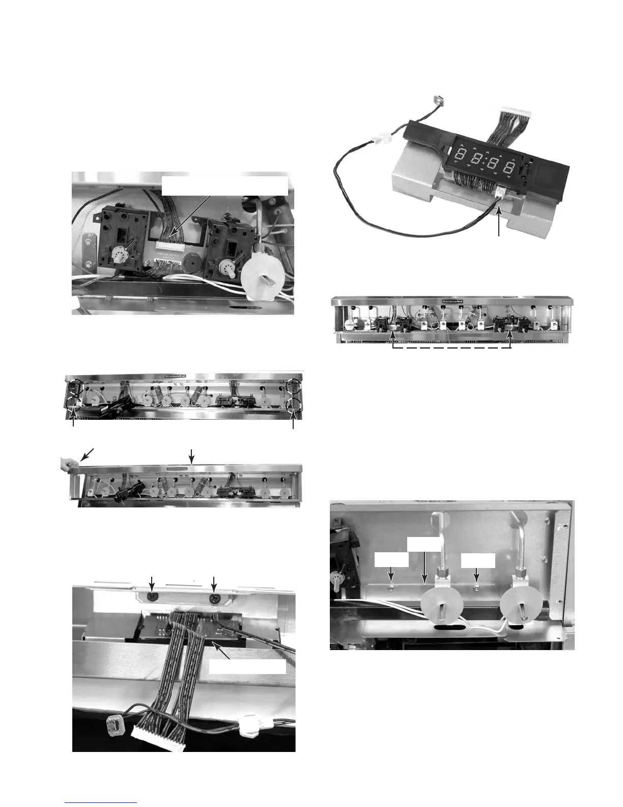
7. To remove a clock:
a) Remove the control panel from the unit
(see step 3 on page 4-4 for the proce-
dure).
b) Disconnect the 12-wire quick discon-
nect from the thermostat & selector
switch assembly.
c) Remove the two left and two right screws
from the front panel frame and remove
the frame from the unit.
d) Remove the two screws from the clock
assembly bracket and remove the as-
sembly from the frame.
e) Disconnect the 2-wire connector from
the clock board.
12-Wire Quick Disconnect
2 Left Screws
2 Right Screws
Front Frame
Remove
Clock Bracket Screws
Clock Assembly
2-Wire Connector
Clock Assembly
a) Remove the control panel from the unit
(see step 3 on page 4-4 for the proce-
dure).
b) Remove the front panel frame (see
step 7 for the procedure).
c) Remove the two hex-head screws from
the left and right shields and remove
the shields.
8. To remove the left or right thermostat &
selector switch assembly:
Thermostat & Selector Switch Assemblies
Shield
Screw
Screw
Continued on the next page.