11
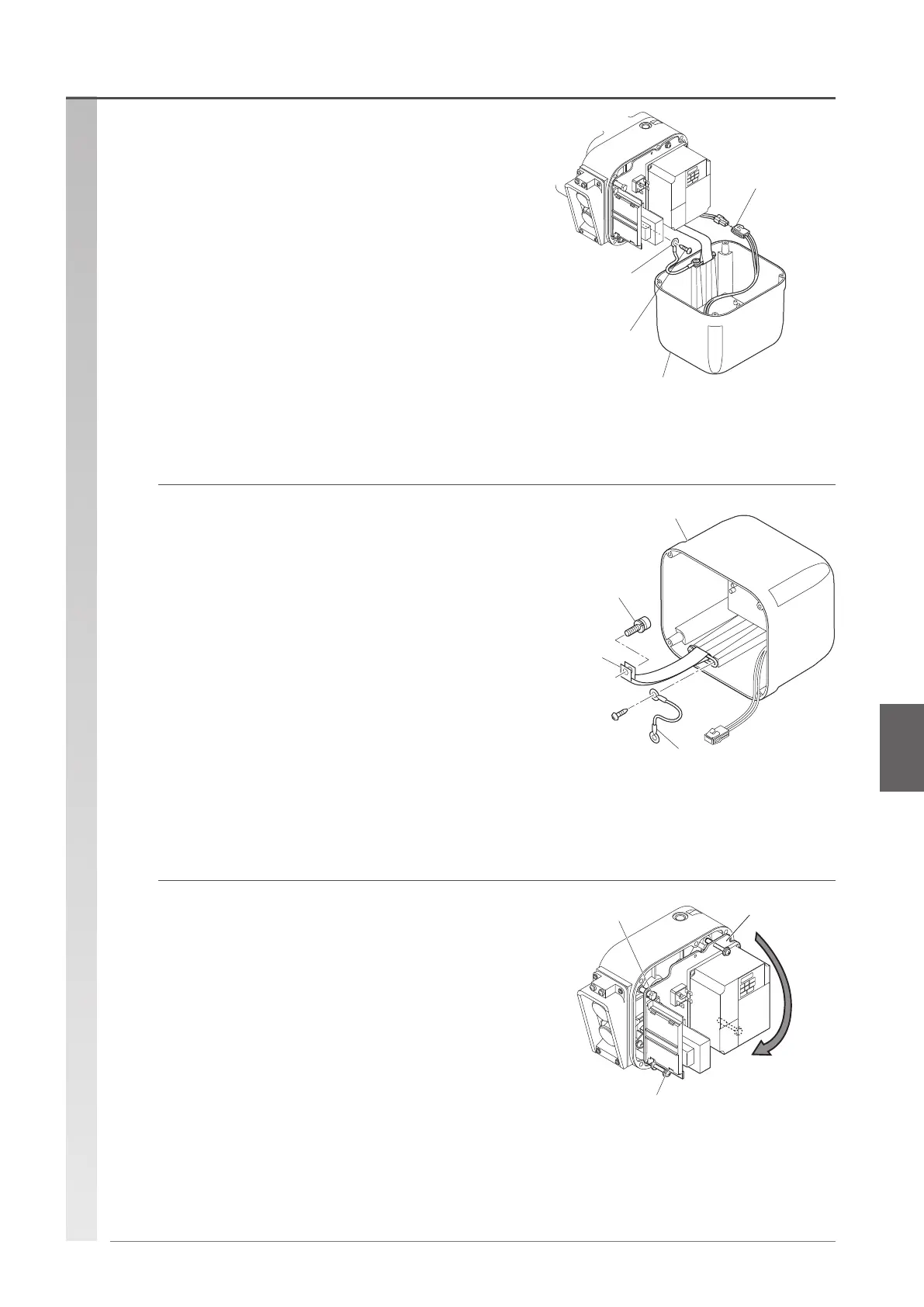
Controller cover
Ground line
Braking resistor
lead wire
Pan-head
machine screw
Controller cover
Socket bolt
(gear case side)
Ground line
Cover belt
Plate screw
Fulcrum pin
Plate
(2) Remove the connector and ground line
connected to the controller cover.
•
To remove the ground line, loosen the pan-head machine
screw of the plate side.
(3) Remove the socket bolt (gear case side)
securing the cover belt, and remove the
controller cover from the gear case.
•
The controller cover can be removed with the cover belt
attached.
(4) Remove the lead wire and connector
between the plate, main body, and inverter,
and remove the plate.
•
Loosen the 3 Plate screws, and turn the plate a little
according to the shape of the fulcrum pin to remove it.
•
Make a note of the locations of the lead wire connections
that will be referred to upon reassembly.
(To be continued)
Disassembly procedure Removing the controller cover

 Loading...