Novar 1xxx KMB systems
15
1.10.1 Output State Indications
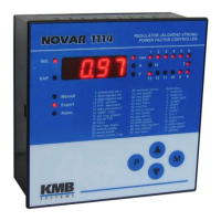
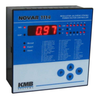
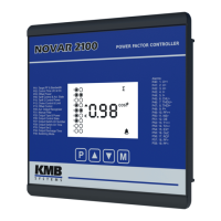
The array of LEDs at the top right of the front panel show the current state of output relays. Each LED
is assigned a number from 1 to 14, and if lit, they indicate closed contacts of the corresponding output
relay.
If a LED is flashing, it means the controller wants to connect the output, but it has to wait for the delay
time to elapse. The corresponding output relay contacts are open and they will be closed as soon as
the reconnection delay time has elapsed.
An exception is the power-up display test to check correct operation of all display elements. In this test
the display shows TEST and all indication LEDs come on and go out one by one. All output relays stay
open while the test is running.
1.10.2 Trend Indication
These LEDs show the magnitude of deviation of the true instantaneous reactive power in the power
system from optimum reactive power value which would correspond to the specified value of required
power factor.
If the deviation is smaller than a half of the reactive power value of the smallest capacitor, both LEDs
are dark. If the deviation is greater than a half of, but smaller than, the reactive power value of the
smallest capacitor, the corresponding LED flashes — if lagging (undercompensation), the IND LED
flashes; if leading (overcompensation), the CAP LED flashes. If the deviation exceeds the value of the
smallest capacitor, the corresponding LED is permanently lit.
Exceptions to these LEDs’ meanings are the following situations:
• measurement U and I method of connection is not defined (parameter 16)
• automatic connection configuration detection process is in progress
• automatic section power recognition process is in progress
If the method of connection is not defined, both LEDs flash; they are dark in the other two situations.
1.10.3 Indication of Manual Mode
Flashing Manual LED indicates that the controller is in the manual mode. The controller’s automatic
control function is disabled.
If this LED is dark and display is in the Measurement mode, the controller is in its standard control
mode or it is carrying out automatic connection configuration detection process or automatic section
power recognition process.
1.10.4 Indication of Backfeed (Power Export)
If the controller knows of the method of connection (measurement voltage and current), that is if the
automatic connection configuration detection process has been completed successfully or the method
of connection has been entered manually, the Export LED indicates the power transmission direction.
If it is dark, the power is flowing from the assumed power supply to the appliance. If the LED is lit, the
power is flowing in the opposite direction.
1.10.5 Alarm Indication
An Alarm relay can be used for non-standard events signalling. This relay’s operation can be set up
as described further below ( parameter 30 ). At Novar 10xx controllers that haven’t dedicated alarm
relay it is necessary to select and set alarm relay function first ( parameter 26 ).
The Alarm LED indicates this relay’s condition, that is if the Alarm relay’s output contact is closed, the
LED flashes.


 To Next Page