Novar 1xxx KMB systems
35
If the parameter is set to 1
11
1, the controller carries out the automatic section recognition power process
every time the controller is powered up, irrespective of the section values having been recognized
before or not.
The process can also be started without interrupting power supply voltage, by editing parameter 20 to
value1
1 1
1 or by controller initialization (see further below).
If the automatic section power recognition process is enabled, it makes no sense to set parameters 21
through 24, therefore these parameters are not shown.
The automatic section power recognition process can be disabled by setting parameter 20 to 0
00
0. In
such an event, sections’ values must be entered using parameters 21 through 24.
Comment : If linear switching mode ( see parameter 21) is set, the automatic section power
recognition process cannot be enabled.
4.1.14 Parameter 21, 22 – Switching Program, Selection of Linear Switching Mode and
Smallest Capacitor (C/ k
MIN
) Nominal Power
If the Automatic Section Power Recognition Process is disabled, these parameters allow entering the
value of each section or setting the “Linear Switching Mode”.
If you select one of the preset combinations for parameter 21 as shown in Table 4.3, you select
a “switching program” that specifies the ratios of all capacitor sections’ values.
When selecting a switching program, the capacitors have to be connected to the controller’s outputs in
sequence where the lowest weight capacitor is connected to output 1. The number of capacitors
connected needs entering in parameter 23. If this number is more than 5, the controller assumes the
weights of sections 6 and higher are the same as the weight of section 5.
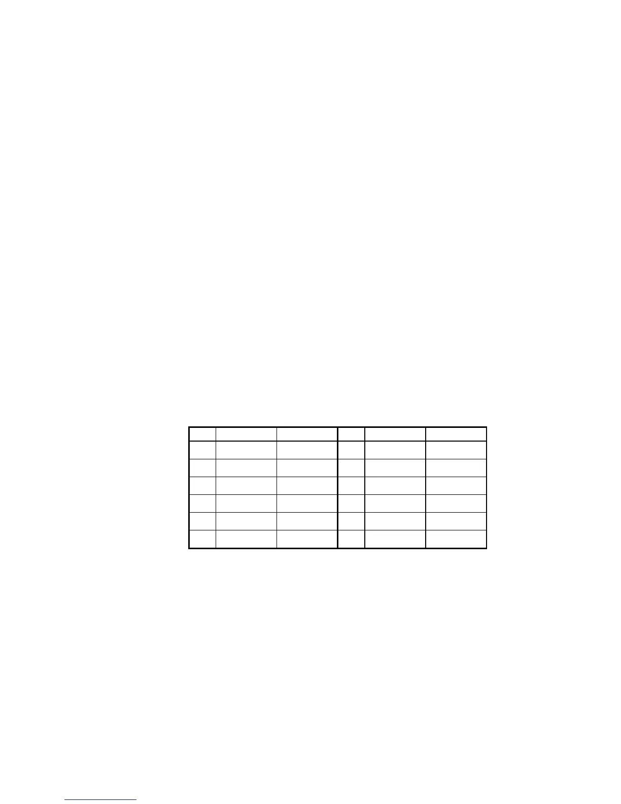
Table 4.3: Switching Program
# combination displayed # combination displayed
1 1:1:1:1:1
1111
11111111
1111
7 1:2:2:2:2
1222
12221222
1222
2 1:1:2:2:2
1122
11221122
1122
8 1:2:3:3:3
1233
12331233
1233
3 1:1:2:2:4
11224
1122411224
11224
9 1:2:3:4:4
1234
12341234
1234
4 1:1:2:3:3
1123
11231123
1123
10 1:2:3:6:6
1236
12361236
1236
5 1:1:2:4:4
1124
11241124
1124
11 1:2:4:4:4
1244
12441244
1244
6 1:1:2:4:8
11248
1124811248
11248
12 1:2:4:8:8
1248
12481248
1248
If none of the preset combinations corresponds to the the combination required, you can enter each
section’s value as you desire by editing parameter 25. In such an event, parameter 21 value
automatically becomes undefined,
---
------
---
, which means “individual switching program”. Parameter 22
thus loses its meaning and it is therefore not displayed.
Having selected the switching program as shown in Table 4.3, you still need to specify the nominal
power value of the smallest (corresponding to weight 1) capacitor C/k
MIN
(parameter 22) in kvar
(although the controller measures in single phase, the value corresponds to the three-phase capacitor
total value). CT ratio (parameters 12, 13) and U
NOM
nominal voltage (parameter 18), possibly also VT
ratio (parameter 17), values have to be already correctly specified in the instrument prior to entering
the aforementioned smallest capacitor power value – only then the smallest capacitor’s nominal value
specified is actual.