Novar 1xxx KMB systems
36
The smallest capacitor nominal value is to be taken from its identification plate or checked by
measuring its phase current with a clamp-on ammeter. Table 4.4 shows phase current values for the
most usual three-phase compensation capacitors.
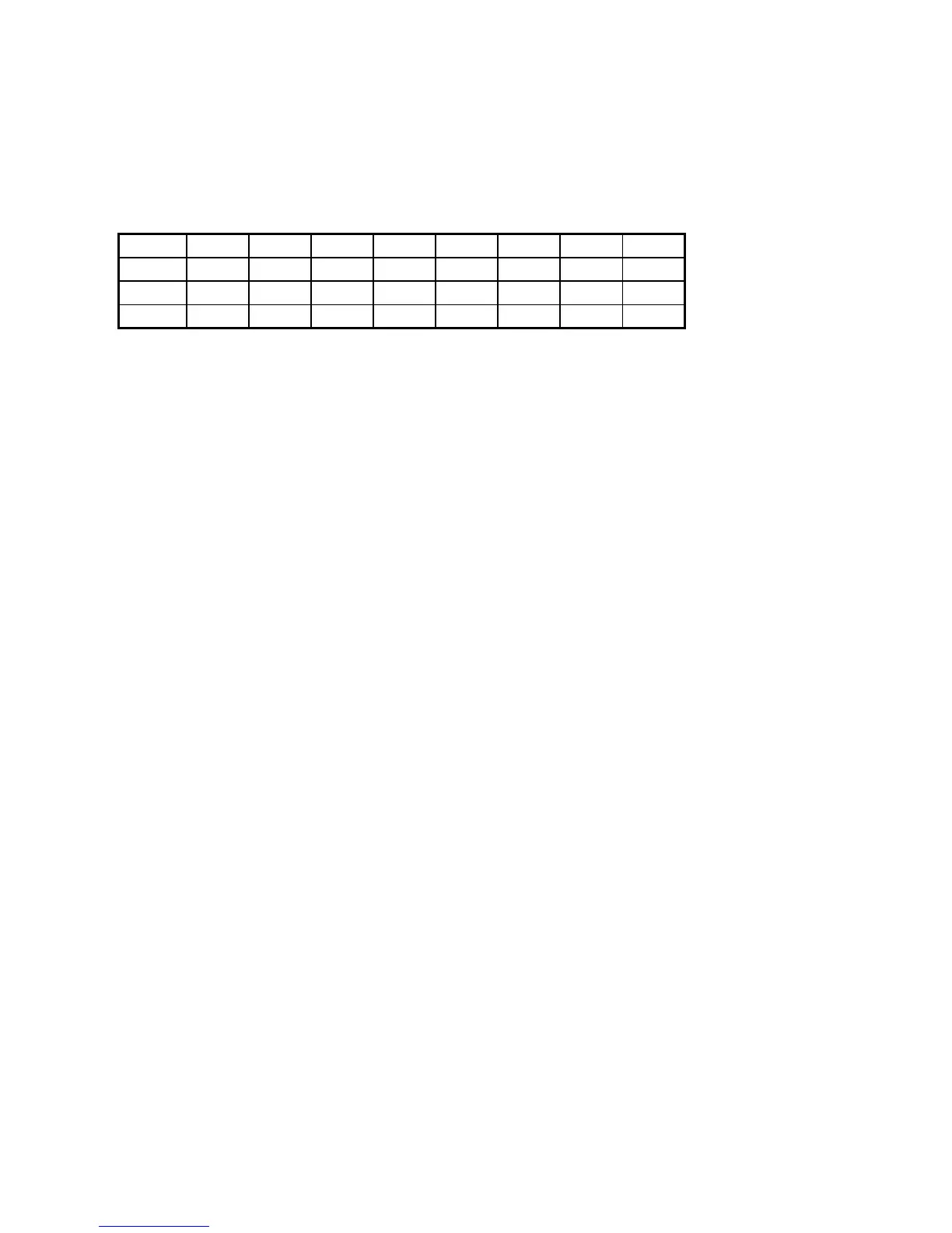
Table 4.4: Capacitor’s Phase Current Value (for Us=400V)
Q [kvar] 2 3.15 4 5 6.25 8 10 12.5
I [A] 2.9 4.6 5.8 7.2 9.0 11.6 14.5 18.1
Q [kvar] 15 20 25 30 40 50 60 100
I [A] 21.7 28.9 36.1 43.4 57.8 72.3 86.7 144.5
If parameter 21 is set to L
LL
L, no switching program is selected (section values have to be entered in
parameter 25) and the linear switching mode is enabled to switch harmonic filters. In this mode the
controller connects or disconnects compensation sections in the linear fashion, which means:
• always the lowest in order not yet connected compensation section(s) is/are connected
• always the highest in order connected compensation section(s) is/are disconnected
Each section that is not permanently connected or permanently disconnected is considered
a compensation section involved in the control process.
On setting the Automatic Section Power Recognition Process (parameter 20) to either A
AA
A or 1
11
1, the
linear switching mode is disabled.
Warning ! It is strongly recommended not to activate linear switching mode at standard power factor
compensation applications, otherwise quality of control process will be decreased.
4.1.15 Parameter 23 – Number of Capacitors
If entering capacitors’ currents manually using the switching program and smallest capacitor power
(parameters 21, 22), it is also necessary to enter the number of capacitors connected – parameter 23.
The value can be set within the range from 1 to the controller’s number of outputs.
If using a smaller number of capacitors than the type of controller allows, it is necessary to connect the
capacitors to outputs starting with output 1 (that is the unconnected outputs will be those with the
highest ordinal numbers).
If the controller outputs are not all used for capacitor connections, the unused outputs can be used to
connect compensation chokes. The controller assumes that the chokes are connected from the lowest
free output up (that is starting with the section following the last capacitor output connected).
These chokes’ currents can be entered in parameter 25, for each choke separately (careful, a choke’s
current must be entered as a negative value – positive polarity currents are considered capacitive
sections by the controller!)
4.1.16 Parameter 25 – Compensation Section Nominal Power
Nominal power of each compensation output can be edited in the side branch of this parameter if
necessary.
The values are displayed in kilovolt-ampere reactive, kVAr, and they correspond to the nominal
three-phase power of the relevant section under voltage corresponding to the compensation system
nominal voltage U
NOM
(parameter 18) value specified. To have the values correspond to the actual
section (capacitor or inductance) compensation power, the current transformer turns ration must be
specified correctly as well (parameters 12, 13) or voltage transformer turns ratio (parameter 17) must.
If these turns ratios are not specified, the section power values are displayed as if the turns ratio is 1.
 Loading...