Novar 1xxx KMB systems
16
2. Installation
2.1 Physical
Instruments designed for a distribution board panel are mounted into a cutout of required size. The
instrument’s position must be fixed with locks.
The Novar1005D and theNovar1007D are designed for mounting on a DIN-35 bar.
Natural air circulation should be provided inside the distribution board cabinet, and in the instrument’s
neighbourhood, especially underneath the instrument, no other instrumentation that is source of heat
should be installed or the temperature value measured may be false.
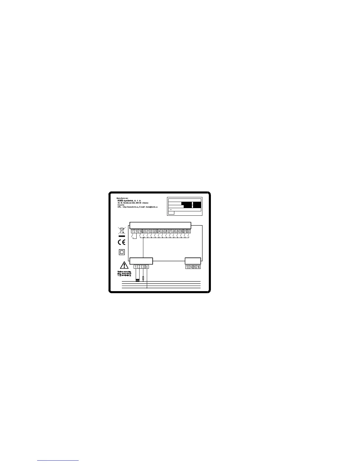
2.2 Connection
To connect the controller there are connectors with screw-on terminals in the back wall. Signal pinout
on these connectors can be seen from the pictures below.
Examples of controller wiring are shown in a separate chapter.
Fig. 2.1 : Novar1114 controller – connectors
L1
L2
L3
N
1 2 3 4 5 6 7
8 9
ALARM
5A
(1A)
max.
10A
100÷275 VAC
k l L N
NOVAR 1106 1114 / 232 485
Serial / vers.:
Product. date :
IP 4X
U 100 275 VAC, 7VA,
÷ ÷
43 67 Hz
LOAD
Maximum cross section area of connection wires is 2.5 square millimetres.
2.2.1 Power Supply
2.2.1.1 Standard Version Controllers
The controller requires supply voltage in the range as declared in technical specifications table for its
operation.
The supply voltage connects to terminals 3 (L) and 4 (N). In case of DC supply voltage the polarity of
connection is free. Power supply voltage needs to be externally protected ( see chapter Protection
below ).
The 12xx line controllers have power supply terminals 3 (L) and 4 (N) internally connected to terminals
5 (L) and 6 (N) which can be used to connect the power supply voltage to measurement voltage input
(terminals 7 – L and 9 – N/L).
Power supply terminal 3 (L) is internally connected to the common pole of output relays. It is
necessary to dimension the power supply protection in consideration of output contactors’ power as
well.
 Loading...