TP-6844 1/13 Section 5 Component Testing and Adjustment 69
7. Check the cold resistance of the stator windings
by connecting the meter leads to stator leads 1-2,
2-3, and 3-1. See Section 1.5, Alternator
Specifications, for stator winding resistances.
Most ohmmeters do not provide accurate
readings below 1 ohm. Low resistance readings
(continuity) and no evidence of shorted windings
(heat discoloration) indicate a stator in good
condition. See Figure 5-10.
Figure 5-10
Figure 5-10 Continuity Test Results on a Good Stator
8. If the resistance test proves inconclusive, use a
megohmmeter to test the stator as described in
the next step.
Note: Because ohmmeter accuracy varies, resistance
readings are approximate readings. Take
readings of the rotor and stator at room
temperature.
Note: Make sure that all stator leads are disconnected
before running the megohmmeter test.
9. Use a megohmmeter to determine whether the
stator is shorted to ground.
a. Apply 500 volts DC to any stator lead and the
stator frame. Perform the megohmmeter test
following the instructions of the megohmmeter
manufacturer.
b. Repeat the test on the other stator leads until
each coil is tested.
Note: A reading of approximately 500 kOhms
(1/2 megohm) and higher indicates a good
stator.
c. Repair or replace the stator if any reading is
less than approximately 500 kOhms. A
reading of less than 500 kOhms indicates
deterioration of the winding insulation and
possible current flow to ground.
5.5 Voltage Adjustments
Testing live electrical circuits. Hazardous voltage or
current can cause severe injury or death. Have trained
and qualified personnel take diagnostic measurements of
live circuits. Use adequately rated test equipment with
electrically insulated probes and follow the instructions of the
test equipment manufacturer when performing voltage tests.
Observe the following precautions when performing voltage
tests: (1) Remove all jewelry. (2) Stand on a dry, approved
electrically insulated mat. (3) Do not touch the enclosure or
components inside the enclosure. (4) Be prepared for the
system to operate automatically. (600 volts and under)
Short circuits. Hazardous voltage/current can cause
severe injury or death. Short circuits can cause bodily
injury and/or equipment damage. Do not contact electrical
connections with tools or jewelry while making adjustments
or repairs. Remove all jewelry before servicing the
equipment.
Note: See Section 3.7 for voltage calibration
instructions.
Voltage Adjustments Using SiteTech
The SiteTech parameters used to adjust the voltage
are shown in Figure 5-11.
Figure 5-11
Figure 5-11 SiteTech Parameters for Voltage
5.5.1 Voltage Regulator Average Voltage
Adjustment
Voltage regulation is performed by the controller. The
controller monitors generator output voltage and
adjusts the Voltage Correction Factor to change the
operating speed range of the generator. The 6VSG
requires no adjustment to maintain rated output
voltage, as the DC output voltage is corrected to the
Voltage Regulator Average Voltage Adjustment as the
generator runs.
Leads Continuity
1 and 2, 2 and 3, 3 and 1
Yes
4 and 5, 5 and 6, 6 and 4
1 and 4, 2 and 5, 3 and 6
1 and 5, 2 and 6, 3 and 4
1 and 6, 2 and 4, 3 and 5
1, 2, 3, 4, 5, or 6 to ground No
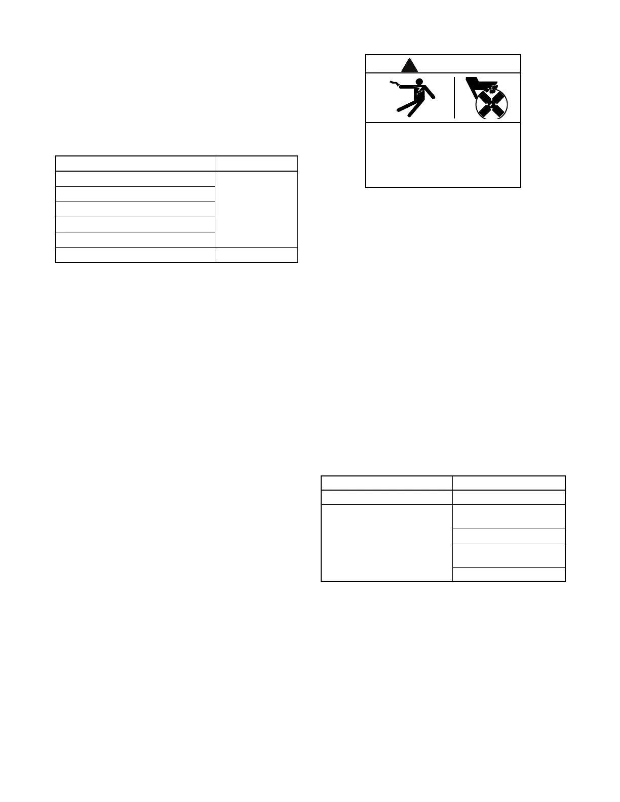
Hazardous voltage. Moving parts.
Can cause severe injury or death.
Operate the generator set only when
all guards and electrical enclosures
are in place.
SiteTech Group Parameter
Genset System Configuration Genset System Voltage
Voltage Regulator Average Voltage
Adjustment
Volts per Hertz Slope
Volts per Hertz Cut-in
Frequency
Voltage Regulator Gain

 Loading...


