82 Section 5 Component Testing and Adjustment TP-6844 1/13
5. Follow the instructions provided with the oxygen
sensor kit to connect the oxygen sensor to the
power supply and A/F reader.
6. Reconnect power to the generator set.
7. Press the RUN button on the controller to start
the generator set.
8. Allow the generator set to run until the engine
reaches normal operating temperature.
9. With the generator set at normal operating
temperature, apply full load (6 kW).
10. After several minutes, note the air/fuel ratio meter
measurements and compare to the λ (lambda)
values in Figure 5-28.
Figure 5-28
Figure 5-28 Acceptable Oxygen Sensor Readings
11. Adjust the fuel metering valve as required to
obtain the output from the oxygen sensor
specified in Figure 5-28.
12. When the fuel mixture is correct, use thread
sealant to seal the metering valve adjustment
screws.
13. Remove the load and allow the generator set to
run unloaded to cool for at least 5–10 minutes.
14. Stop the generator set by pressing the OFF
button on the controller.
15. Disconnect the generator set engine starting
battery, negative (–) lead first.
16. Disconnect power to the generator set.
17. Allow the generator set exhaust system to cool.
18. Disconnect the DVM leads from the oxygen
sensor.
19. After the sensor has cooled, remove the oxygen
sensor from exhaust manifold.
20. Apply a small amount of antiseize compound to
exhaust plug and reinstall the plug into the
exhaust manifold.
21. Reconnect the generator set engine starting
battery, negative (–) lead last.
22. Reconnect power to the generator set.
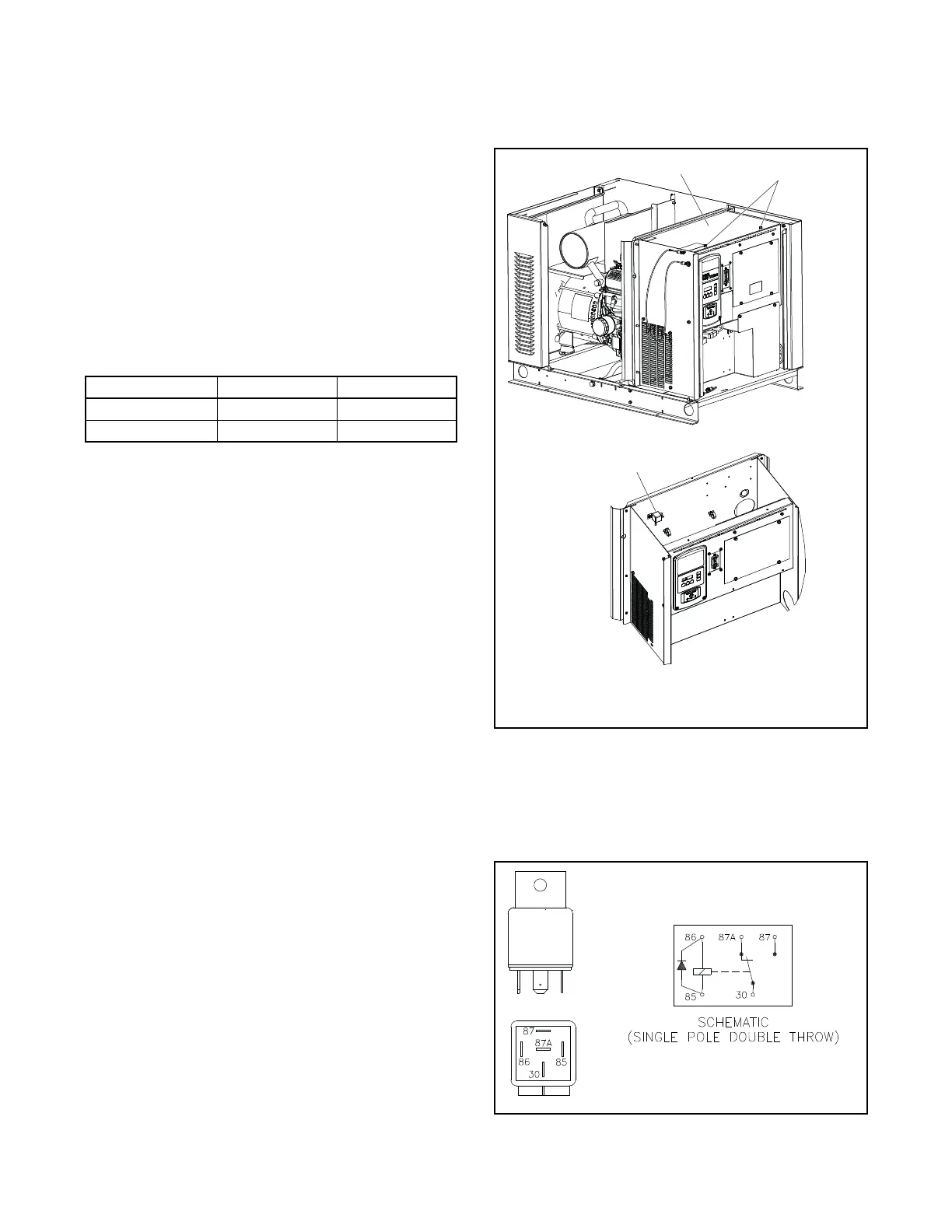
5.9 Starter Relay
The starter relay is located behind the controller. See
Figure 5-29.
Figure 5-29
Figure 5-29 Starter Relay Location
The starter relay contains an internal diode across the
relay coil. See Figure 5-30. Continuity checks across
the coil terminals will show continuity (low resistance)
in one direction and an open circuit in the other.
Figure 5-30
Figure 5-30 Starter Relay
Fuel Lambda (λ) UEGO, VDC*
* UEGO sensor readings shown for reference.
LPG 0.944–0.966 2.60 ± 0.05
Natural Gas 1.063–1.091 2.10 ± 0.05
KPS_093
3
1
2
ADV-8060
GM80535
1. Cover
2. Screws
3. Starter relay
KPS_094
259391

 Loading...


