TP-6844 1/13 Section 5 Component Testing and Adjustment 79
5.8.1 Fuel Solenoid Valve
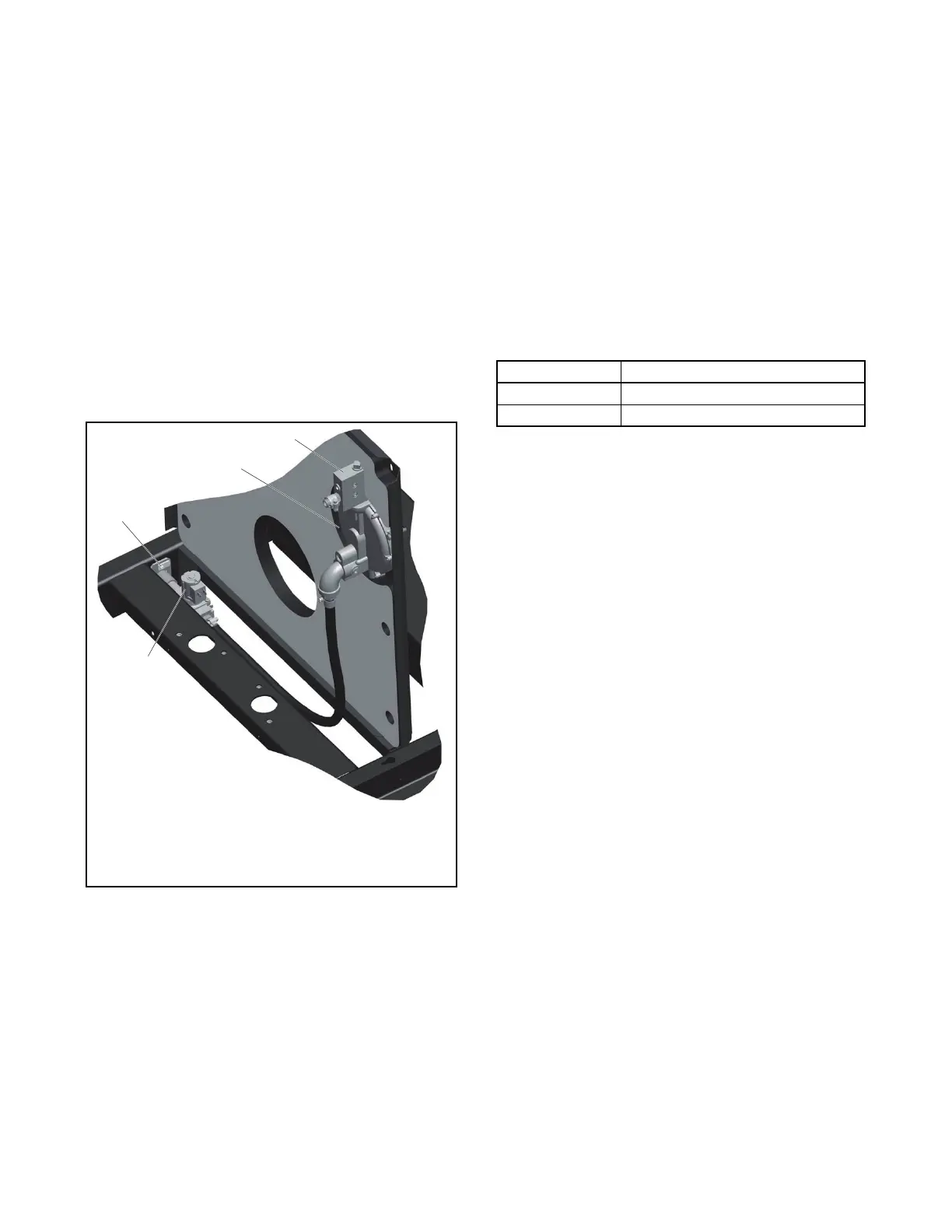
A solenoid valve upstream of the regulator and the
flexible fuel connector provides automatic fuel on/off
control. See Figure 5-23. The engine starting battery
powers the solenoid valve and the engine starting
controls open the valve when the engine cranks or
runs.
Fuel Valve Operation Test Procedure
1. Disconnect the positive (+) battery lead from the
gas valve terminal.
2. Apply 12 VDC to the gas valve terminal and listen
for an audible click, indicating that the valve
actuates.
3. Replace the gas valve if it does not actuate in
step 2.
Figure 5-23
Figure 5-23 Fuel System
5.8.2 Fuel Regulators
The typical gaseous fuel system uses two regulators.
The primary regulator reduces the line pressure to an
allowable inlet pressure for the secondary regulator.
The fuel supplier provides and maintains the primary
regulator. The secondary regulator is factory-installed
on the generator set and is designed for a maximum
inlet pressure of 2.7 kPa (6 oz./in.
2
) or 280 mm (11 in.)
water column.
Note: Do not attempt to adjust the fuel mixture or
engine speed by adjusting the regulators.
The fuel lockoff prevents fuel flow when the engine is
not operating. See Figure 5-25. Do not try to adjust
the fuel pressure, fuel mixture, or engine speed using
the fuel lockoff.
Checking the Fuel Pressure
Use a gauge or manometer to check the fuel pressure
at the secondary regulator inlet. See Figure 5-25.
Measure the fuel pressure with the generator set
running at rated load. Contact the fuel supplier if the
inlet pressure is not within the range shown in
Figure 5-24.
Figure 5-24
Figure 5-24 Fuel Pressure Requirements
1. Regulator
2. Fuel block
3. Fuel solenoid valve
4. Fuel inlet, 1/2 in. NPT
female
Fuel Fuel Pressure Required
Natural Gas 1.2–2.7 kPa (5–11 inches H
2
O)
LPG 1.7–2.7 kPa (7–11 inches H
2
O)

 Loading...


