40 Section 3 Controller TP-6844 1/13
3.6 Controller Setup
Controller setup is required after installation. Follow
the instructions in this section to set the necessary
parameters.
If a personal computer (laptop) and Kohler
®
SiteTech
®
software were used to create a controller settings file
at the time of generator set installation (when the
controller was known to be operating correctly), then
SiteTech software can be used to load the saved
settings onto the new controller. See TP-6701,
SiteTech Software Operation Manual, for instructions
to export and import controller settings.
Note: Load the old controller settings to the new
controller only if you are certain that the settings
are correct. Many generator set operation
problems can be caused by incorrect settings.
If a controller setting file is not available, follow the
instructions in this section to set the parameters using
the controller menus and/or SiteTech software.
Controller Setup Notes:
• Some of the required information can be found on
the generator set nameplate. See Figure 3-12 for
the nameplate location.
• For the Genset Model Number, select 6VSG-24V for
the 24V VSG, 6VSG-36V for the 36V VSG, or
6VSG-48V for the 48V VSG.
• Setting the model number will automatically set the
system parameters to the default settings. Check
the system parameters listed in Figure 3-15 and
adjust if necessary. See Section 3.3.1 for more
information.
Controller Setup Procedure
1. Use one of the following methods to set the
parameters shown in Figure 3-15.
a. Use the buttons on the controller to navigate
through the controller menus and change the
settings. See the required controller menus in
Figure 3-16 and Figure 3-17. See the
generator set operation manual for additional
instructions, if necessary.
b. Use a personal computer and Kohler
®
SiteTech
®
software.
c. Use Kohler
®
OnCue
®
software (version 3.1 or
higher) and a personal computer connected
directly to the controller with a USB cable to
set the genset serial number and model. See
Section 3.2 for the USB connection.
2. Check the voltage calibration and adjust, if
necessary. See Section 3.7, Voltage Calibration.
3. Verify that the voltage regulator gain is set to 128.
Use SiteTech to adjust, if necessary.
4. If the generator set is connected to a
programmable Interface Module (PIM), use
SiteTech to set the digital inputs and outputs.
5. If the generator set is equipped with the
factory-installed communications kit, use
SiteTech to set the Personality Installed Options
parameter to 6VSG Telecom.
6. If OnCue
®
is used to monitor this generator set,
reset the OnCue password on the controller and
note the new password. See Section 3.9, Setting
the OnCue Password. Then connect with OnCue
and enter the new password. Verify that OnCue
can communicate with the generator set over the
Internet before leaving the job site.
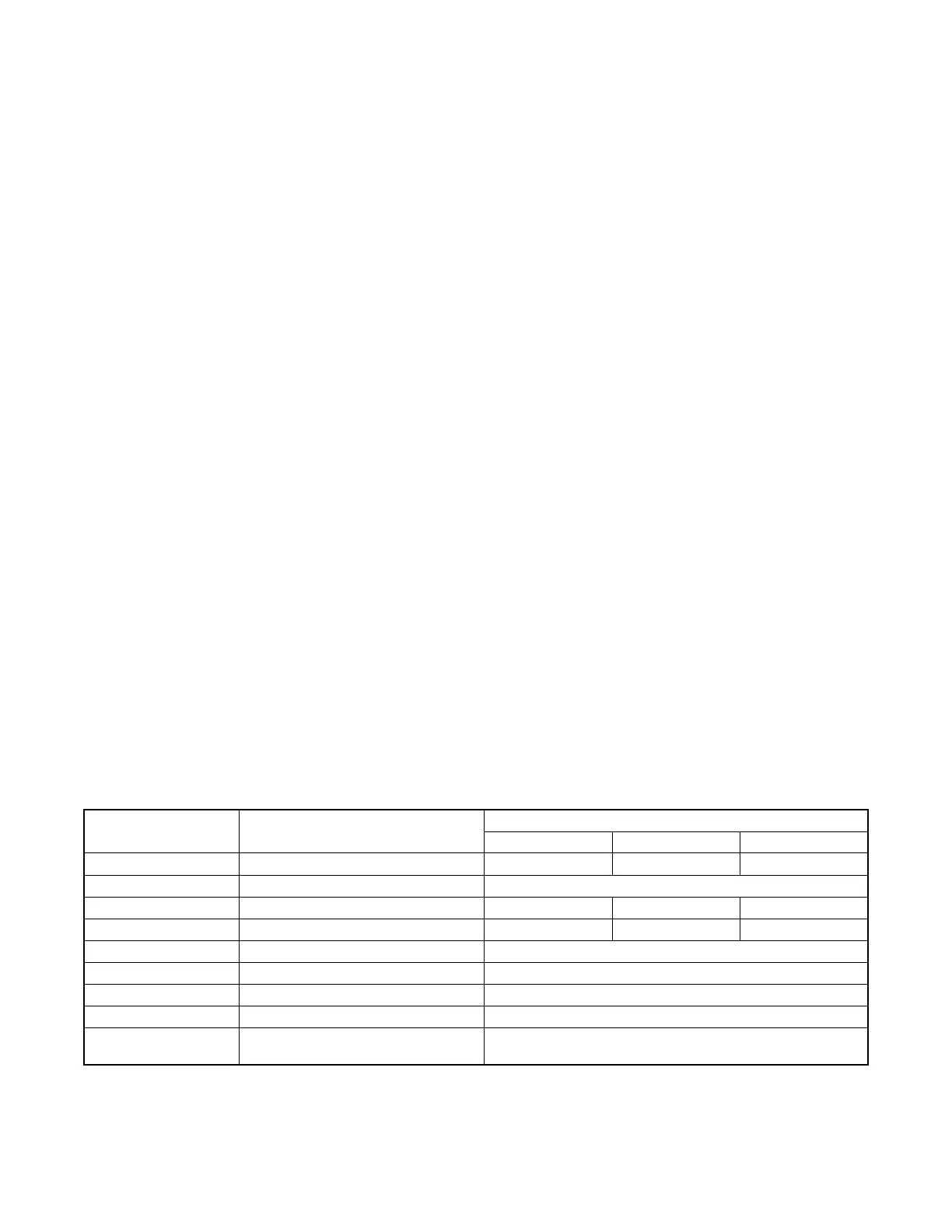
Figure 3-15
Figure 3-15 Controller Setup
Controller Parameter SiteTech Parameter
Settings
24V 36V 48V
Genset M/N Genset Model Number 6VSG-24V 6VSG-36V 6VSG-48V
Genset S/N Genset Serial Number From nameplate
System Voltage Genset System Voltage 27 * 47.5 * 54 *
Auto Start Volt Auto Start Minimum Voltage 25 * 37.5 * 50 *
Auto Stop Load (%) Auto Stop Minimum Percent Load 40 *
Pct. Load Limit (%) Genset Maximum Percent Capacity 100 *
Fuel Type Genset Fuel Type Natural Gas or LPG
— Voltage Regulator Gain † 128
— Personality Installed Options †
(in Genset Personality Profile Group)
None for standard 6VSG;
6VSG Telecom if communications kit is installed.
* Setting the Model Number automatically sets these parameters to the default settings shown. See Section 3.3.1 for
information about these parameters.
† SiteTech is required to adjust these parameters.

 Loading...


