TP-6844 1/13 Section 3 Controller 39
Figure 3-13
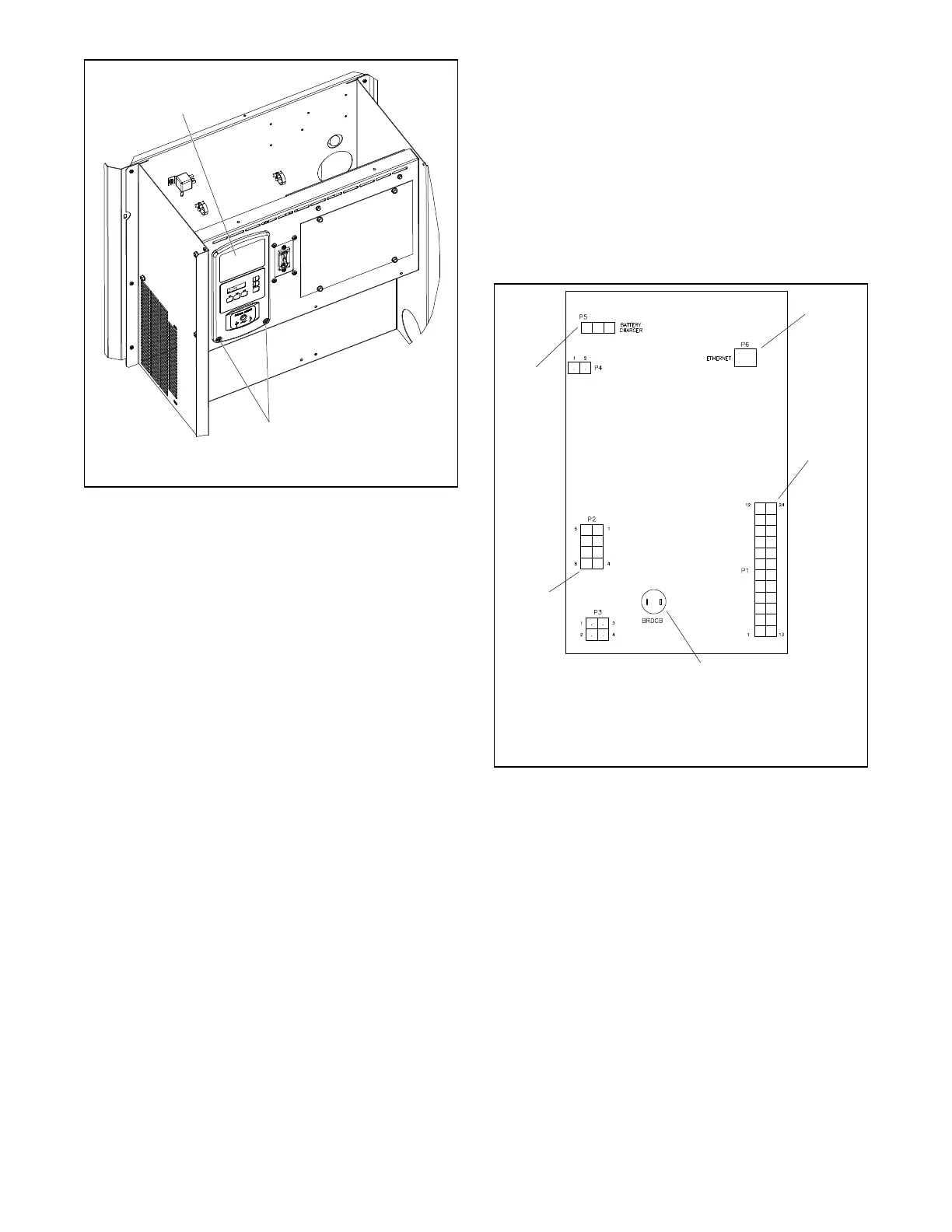
Figure 3-13 Controller Mounting
6. Note the connections on the back of the
controller, and then disconnect all harnesses and
leads from the controller. See Figure 3-14 or the
wiring diagram.
7. Remove the old controller.
8. Reconnect all harnesses to the new controller
assembly.
9. Install the controller onto the junction box using
the two screws removed in step 5.
10. Reconnect the engine starting battery, negative
(–) lead last.
11. Reconnect the power to the generator set by
closing the circuit breaker in the distribution
panel.
12. The controller will prompt you to set the date and
time, and then to set the exerciser. See the
generator set Operation Manual for instructions, if
necessary.
13. Check the firmware version on the controller.
See Section 3.4. Use SiteTech or OnCue with
the computer connected to the controller’s USB
port to update the firmware to the latest released
version. See the OnCue Operation Manual or the
SiteTech Software Operation Manual for
instructions.
14. Set up the controller as instructed in Section 3.6,
Controller Setup.
15. Calibrate the voltage. See Section 3.7, Voltage
Calibration.
16. If OnCue
®
is used to monitor this generator set,
reset the OnCue password on the controller and
note the new password. See Section 3.9, Setting
the OnCue Password. Then connect with OnCue
and enter the new password.
17. Verify that OnCue
®
can communicate with the
generator set over the Internet before leaving the
job site.
Figure 3-14
Figure 3-14 Controller Connections
1. Controller 2. Controller mounting
screws (qty. 2)
2
KPS_072
1
4
5
3
VSC CONTROLLER
1. P6 Ethernet connection
for OnCue
2. P1
3. Not used
4. P2
5. P5

 Loading...


