68 Section 5 Component Testing and Adjustment TP-6844 1/13
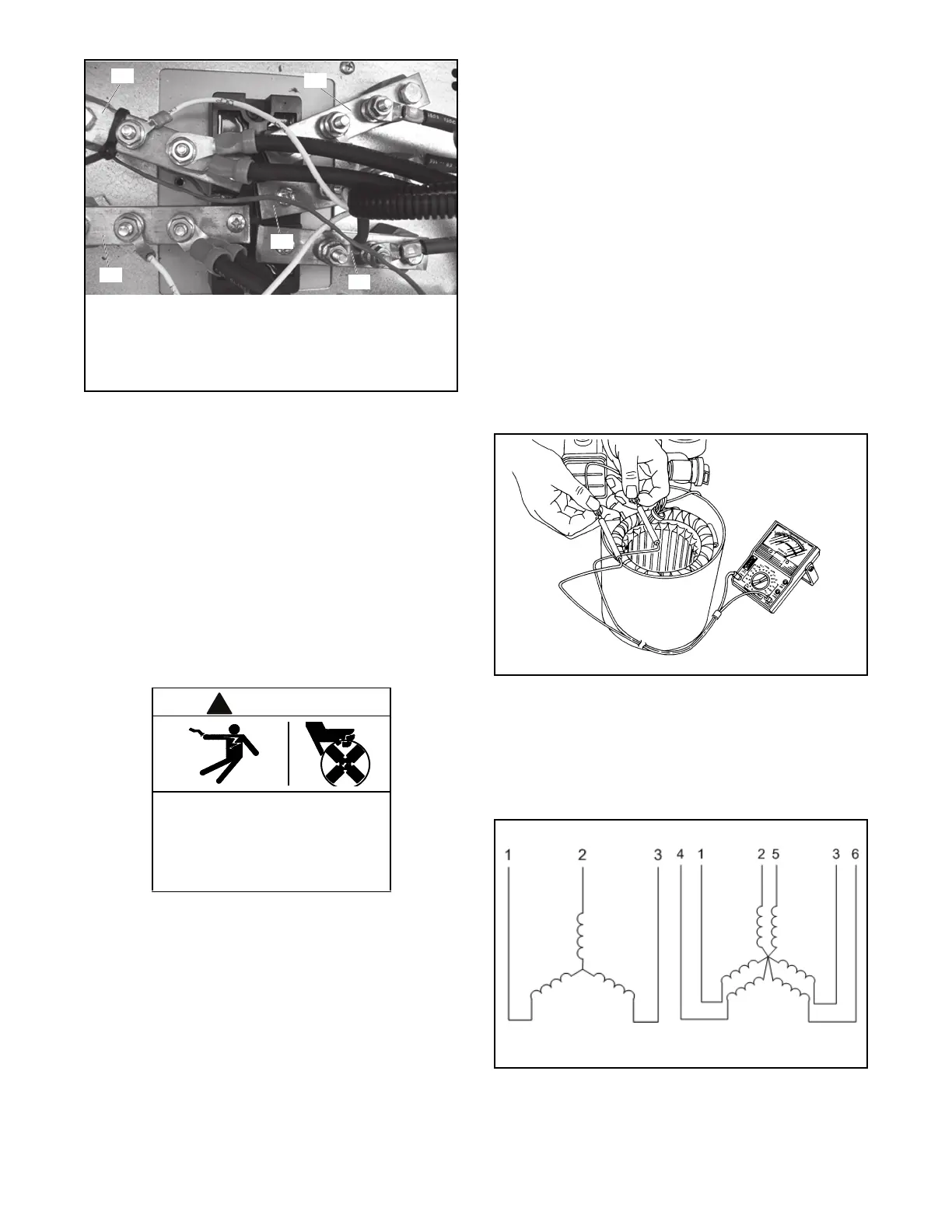
Figure 5-7
Figure 5-7 DC Voltage Test
5.4 Stator
The stator contains a series of coils of wire laid in a
laminated steel frame. The stator leads supply AC
voltage to the load and voltage regulator. Before
testing the stator, inspect it for heat discoloration and
visible damage to housing lead wires, exposed coil
windings, and exposed areas of frame laminations. Be
sure the stator is securely fastened to the stator
housing.
Note: Disconnect all stator leads before performing all
stator tests.
High voltage test. Hazardous voltage can cause severe
injury or death. Follow the instructions of the test
equipment manufacturer when performing high-voltage tests
on the rotor or stator. An improper test procedure can
damage equipment or lead to generator set failure.
Short circuits. Hazardous voltage/current can cause
severe injury or death. Short circuits can cause bodily
injury and/or equipment damage. Do not contact electrical
connections with tools or jewelry while making adjustments
or repairs. Remove all jewelry before servicing the
equipment.
Stator Continuity and Resistance Tests
1. Press the OFF button on the controller to turn off
the generator set.
2. Disconnect power to the generator set (if
equipped).
3. Disconnect the generator set engine starting
battery, negative (–) lead first.
4. Disconnect all stator leads before performing all
stator tests.
5. To check for stator continuity, set the ohmmeter
on R x 1 scale. First set the ohmmeter zero by
holding the red and black meter leads together
and setting the ohmmeter reading to zero. Then
check the stator continuity by connecting the
meter leads to the stator leads as shown in
Figure 5-8.
Figure 5-8
Figure 5-8 Testing Stator Windings
Note: For 24V units, 1, 2, 3, 4, 5, and 6 are the
generator output leads. For 36 and 48V units,
leads 1, 2, 3 are the generator output leads.
Refer to the schematic in Figure 5-9 when
performing the following steps.
Figure 5-9
Figure 5-9 Single-Phase Alternator Stator Leads
6. Contact the ohmmeter leads and readjust the
ohmmeter to read zero ohms.
Hazardous voltage. Moving parts.
Can cause severe injury or death.
Operate the generator set only when
all guards and electrical enclosures
are in place.
1. DC +
2. DC –
3. AC 1
4. AC 2
5. AC 3
KPS_115
Stator Testing
36V and 48V units 24V units

 Loading...


