TP-6844 1/13 Section 5 Component Testing and Adjustment 67
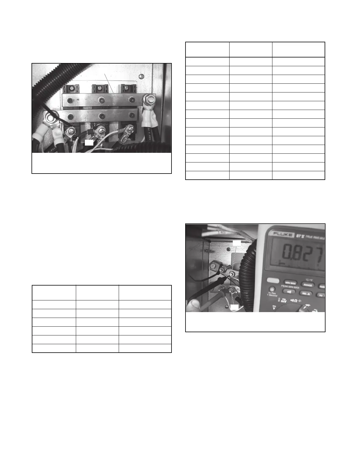
With the generator running at no load and with the
output circuit breaker open, check the DC output of the
rectifier (between the + and – terminals, most easily
found by the connection of the DCP and DCN wires
going to the controller).
Figure 5-3
Figure 5-3 DC Output
If the DC voltage is close to the generator rating,
measure the AC voltage on the DC output. This value
should be less than 10% of the measured DC value if
the rectifier is working correctly.
Alternatively, it is possible to test the rectifier with the
generator stopped, the output breaker open and the
stator leads to the alternator disconnected. To test the
rectifier in this manner, a multimeter capable of
measuring forward-bias voltage of a diode is
necessary. Measure the diodes as shown in
Figure 5-4 or Figure 5-5. Repeat the measurements
for all three diodes.
Figure 5-4
Figure 5-4 24V 6VSG Units
If conduction is found when measuring the diode
forward drop with + lead on pin 2 and – lead on pin 1 of
the diode assembly, one of the diodes may be
damaged. Disconnect the bus bar tying the three
diode blocks together and retest each block. If a block
has conduction when connecting a multimeter with +
lead on pin 2 and – lead on pin 1 of the diode
assembly, it may be damaged. If all three have
conduction, it is possible that the multimeter in use is
not intended for measuring high power diodes.
Figure 5-5
Figure 5-5 36V and 48V 6VSG Units
If all tests appear to have diode conduction, it is
possible that the multimeter in use is not intended for
measuring high power diodes.
Figure 5-6
Figure 5-6 DC Voltage Test
Negative Lead
Test Point
Positive Lead
Test Point
Diode Forward
Voltage Drop
Pin 2 Pin 3 0.1V to 0.6V
Pin 2 Pin 1 0.2V to 1.2V
Pin 3 Pin 1 0.1V to 0.6V
Pin 3 Pin 2 No diode conduction
Pin 1 Pin 2 No diode conduction
Pin 1 Pin 3 No diode conduction
KPS_112
1
2
Negative Lead
Test Point
Positive Lead
Test Point
Diode Forward
Voltage Drop
AC1 DC – 0.1V to 0.6V
AC2 DC – 0.1V to 0.6V
AC2 DC – 0.1V to 0.6V
DC + AC1 0.1V to 0.6V
DC + AC2 0.1V to 0.6V
DC + AC2 0.1V to 0.6V
DC – AC1 No diode conduction
DC – AC2 No diode conduction
DC – AC2 No diode conduction
AC1 DC + No diode conduction
AC2 DC + No diode conduction
AC2 DC + No diode conduction
DC + DC – 0.2V to 1.2V
DC – DC + No diode connection
KPS_113
1
2

 Loading...


