74 Section 5 Component Testing and Adjustment TP-6844 1/13
Check the stepper motor, carburetor, and
linkage.
8. To test controller’s governing function, open the
generator set circuit breaker, disconnect the
engine starting battery, and shut off the fuel
supply.
9. Disconnect the stepper motor plug P6 to access
the stepper motor terminals.
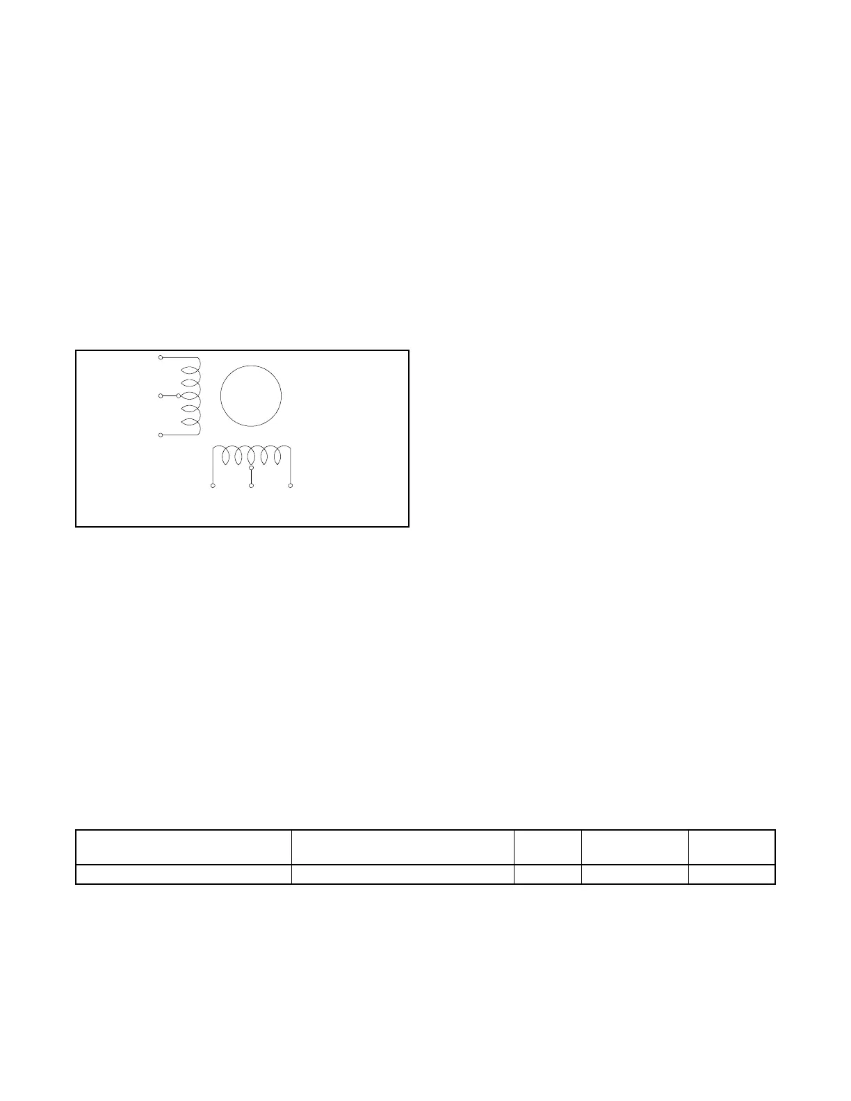
10. Check the stepper motor coil resistance across
pins 2 and 3 and across pins 1 and 4. Only two
stepper motor leads of each coil group are used
(BLK-YEL and RED-WHT). See Figure 5-15.
The resistance per half coil is 38.5 ohms. If one
of the coils has a significantly higher resistance or
is shorted, replace the stepper motor.
Figure 5-15
Figure 5-15 Actuator Coil Group
11. Inspect the linkage and the bushings between the
stepper motor and the carburetor for damage.
Replace as necessary.
12. Disconnect the linkage between the stepper
motor and the carburetor. Verify free, full range of
motion for the stepper motor and the carburetor
throttle plate. Replace as necessary.
13. If there is power and a good ground connection to
the controller and the stepper motor, and the
carburetor and linkage pass the checks of steps
10 through 12, the problem may be with the
controller. Check controller connections, wiring,
and settings. Refer to the troubleshooting
procedures in Section 4.
5.6.5 Engine Speed Gain Adjustment for
the Governor
Note: Adjusting the governor gain may cause the
generator to operate incorrectly.
Note: Typical governor gain settings are between 35
and 65. Settings outside this range are not
recommended for extended use
(troubleshooting only).
The governor gain controls how much throttle
movement is tied to a given change in the generator
speed or target speed. Higher gains make the throttle
move more aggressively on a speed change; lower
gains make the throttle move more slowly.
Using Kohler SiteTech, adjust the Engine Speed Gain
Adjustment setting in the Engine Speed Governor
group. See Figure 5-16. Change the governor gain
setting in small steps (5 or less).
• If the engine is hunting slowly (changes from
maximum to minimum speed in more than a
second), increase the governor gain.
• If the generator is hunting quickly (maximum to
minimum speed several times per second),
decrease the gain.
• If changing the gain makes the hunting worse, try
changing the gain in the other direction.
5.6.6 Advanced Speed Control
Note: Do not adjust the Advanced Speed Control
settings unless instructed to do so by the Kohler
Generator Service Department.
The four parameters under Advanced Speed Control
also permit adjustment of the governor function, but
have the potential of dramatically affecting the load
transient performance of the generator. They are set
in the factory and are tested to comply with factory
performance standards. They should never be
changed from the factory settings except under the
direction of factory personnel.
Figure 5-16
Figure 5-16 Engine Speed Governor Parameter in SiteTech
PIN 3, BLK
PIN 2, YEL
PIN 5, GRN
(not used)
PIN 4,
RED
PIN 1,
WHT
PIN 6, BLUE
(not used)
KPS_085
SB-555
SiteTech Group Parameter Units
Adjustment
Range
Default
Setting
Engine Speed Governor Engine Speed Gain Adjustment 35 – 65 50

 Loading...


