M-SS-017-07 Rev C 10 SERVOSTAR CD
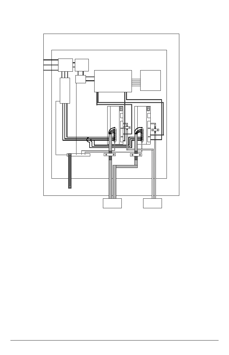
CX FILTER AND BONDING DIAGRAM
Cabinet/Enclosure
CDCD
Routed to
Motors
Controller I/O
Routed to
Motors
Contactor,
Fuses,
Xfmr,
etc.
230
VAC
XFMR
CNC / PLC / Controller
EMI
filter
EMI
filter
Back Plane
2
3
4
5
6
7
8
9
1
Note 1
Input power enters enclosure from metal conduit. This
eliminates the need for shielded input power cable.
Note 2
Single point ground. A bus bar (ground bus) is an
excellent way to achieve this.
Note 3
High frequency ground between non-conductive back
panel and enclosure. Also, a high frequency ground is
required between the enclosure and earth ground.
Note 4
EMI filter grounding. Safety grounds must be provided
on the filters. Hazard potentials exist even when the
power is off because of the capacitors internal to the
filters.
Note 5
Bonding of motor cables. The use of armored
(screened) motor cables bonded as close to the drive
as possible are essential for CE compliance and
strongly recommended to better the overall
performance and reliability of the system.
Note 9
Motor cables and feedback cables exiting the cabinet going to the motor should be
separated as much as possible. Ideally, the use of separate conduits provides good isolation,
which can limit coupling of noise from motor to feedback cables.
Note 6
Feedback cable bonding is required for CE compliance. As with the motor cables, the
feedback cables should be bonded to the back panel. This bonding does two things. First, it
cuts down radiation from the drive, which may be in the form of high frequency energy
resulting from internal processor clocks. Second, it provides immunity for the drive. Since the
feedback device is located internal to the motor, it is going to pick up some noise currents and
transmit them along the feedback cable. The bonding directs the currents from the shield of
the feedback cable to back panel ground. This reduces the amount of noise entering the
drive.
Note 7
AC power lines that must be routed past other lines (such as motor cables or I/O lines) should
cross at a 90º angle. This minimizes the coupling effect. Additionally, the power lines should
be routed as close to the back panel as possible. Any noise currents on the lines are
capacitively coupled to the ground plane and not to other lines.
Note 8
Control (I/O) signals should be kept separate from all power and motor cables, if possible.
Keep control wiring as short as possible and use screened wire. Bonding is also
recommended but not required for CE compliance. A separation distance of 20 cm. (8 in.) is
sufficient in most cases. Where control cables must cross power cables, they should cross at
a 90º angle.

 Loading...


