M-SS-017-07 Rev C 17 SERVOSTAR CD
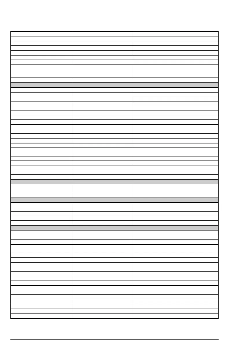
PRODUCT FAMILY CONTROL SPECIFICATIONS
Current Loop Update Rate 62.5 ?S (16 kHz)
Bandwidth <2000 Hz
Commutation Loop Update Rate 62.5 ?S (16 kHz)
Max. Commutation Frequency 400Hz
Output Waveform Sinusoidal
Velocity Loop Update Rate 250 ?S (4k Hz)
Bandwidth <400 Hz
Speed Command Resolution
Serial: 1 RPM or 1mm/sec or VLIM/16384
Analog: (1/6554) * VMAX
Long-term Speed Regulation 0.01% (?P clock tolerance)
Position Loop Update Rate 500 ?S (2 kHz)
I/O Connector (C3 by pinout)
Analog Input (2, 3) Absolute Maximum Voltage 13 V differential
Input Resolution 14 Bit/1.2
Sensitivity 1.53 mV min
Voltage Range
-10V to +10V = -120% Motor rated speed to +120%
Motor rated speed (Adjustable Vscale parameter)
Input Impedance/CMR > 10 K? /50 dB
Long-term Drift 100 ppm (0.075%/?C)
Fault Output Relay (5, 6) Max Capacity 1 A at 24 VDC
Remote Enable (7, 8)
Configurable Inputs(7, 9, 10, 11)
Bandwidth 2.5 kHz (Opto-isolated)
Input Voltage Range 12 V to 24 V Nominal (bi-directional)
Min. On/Max. Off 10 V/1 V
Current Demand per Input 20 mA (max)
Configurable Digital Output (7, 12) Output Voltage (max.)
0 V to 48 V Nominal – bi-directional (Open
Collector)
(Min. On) 1V
Max. Output Current 60 mA
Configurable Analog Output (13, 4) Max. Output Current 1 mA (1 K? internal series resistance)
Sensitivity / Resolution 4.9 mV/12 Bit
Voltage Range -10 V to +10V
Encoder Equivalent Output (C4 by pinout)
A/B/I & Complements
(1, 2, 4, 5, 7, 8)
Output Voltage (high level) at 25?C 2.5 V min. at 20mA Differential
RS 485 Line Drive Type DS26C31TM
Remote Encoder Input (C8 by pinout)
A/B/I & Complements
(1, 2 ,4, 5, 7, 8)
Input Voltage at 25?C ±5 V Differential
Input Sensitivity ±0.2V
Input Impedance 100?
RS 485 Line Receiver Type SN75173
Extended I/O Connector (C9 by pinout)
Analog Input (A1, B1) Absolute Maximum Voltage 12.5 V differential
Input Resolution 14 Bit
Sensitivity 1.53 mV min
Voltage Range
-10V to +10V = -120% Motor rated speed to +120%
Motor rated speed (Adjustable Vscale parameter)
Input Impedance/ CMR > 10 k ?/50 dB
Long- term Drift 100 ppm (0. 075%/ ?C)
Configurable Inputs
(A3, B3, A4, B4, A5, A6, B6, A7))
Bandwidth 4.6 kHz (Opto- isolated)
Input Voltage Range 12 V to 30 V typical, 24 V Nominal (bi- directional)
Min. On/ Max. Off 10 V/ 1 V
Current Demand per Input 20 mA (max)
Configurable Digital Outputs
(A8, B8,A9, B10)
Output Voltage (max.)
0 V to 48 V Nominal – uni- directional (Opto isolated
Open Collector) type Source
(Min. On) 1V
Max. Output Current 60 mA
Configurable Analog Output (B2) Max. Output Current 1 mA (1 K ??internal series resistance)
Sensitivity / Resolution 4.9 mV/ 12 Bit
Voltage Range -10 V to +10V
See the section on Position Loop in for features using this input.
A flyback diode is necessary for inductive loads connected across the 01 output.
Extended I/O (C9) only A3,B3 and B4 are available.

 Loading...


