50 Disassembly and assembly SEN01057-01
PC800, 850-8
5
Removal and installation of main
pump assembly 1
Special tools
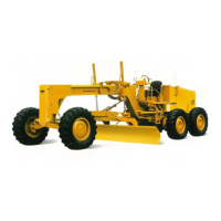
a Figure to the left: pin gauge, figure to the right:
micrometer for the bore
Removal
k Lower the work equipment to the ground
and stop the engine.
k Loosen the cap of the hydraulic tank gradu-
ally to release the internal pressure of the
hydraulic tank.
k Disconnect the cable from the negative (–)
terminal of the battery.
a Before disconnecting the hoses and tubes,
make match marks on them. After disconnect-
ing them, install oil stopper plugs to them.
1. Remove the counterweight assembly. For
details, see “Removal and installation of coun-
terweight assembly”.
2. Remove pump undercovers (1) and (2).
3. Remove the hydraulic tank strainer and stop
the oil with oil stopper tool S1.
q When not using tool S1, remove the drain
plug and drain the oil.
6 Hydraulic tank: Approx. 470 l
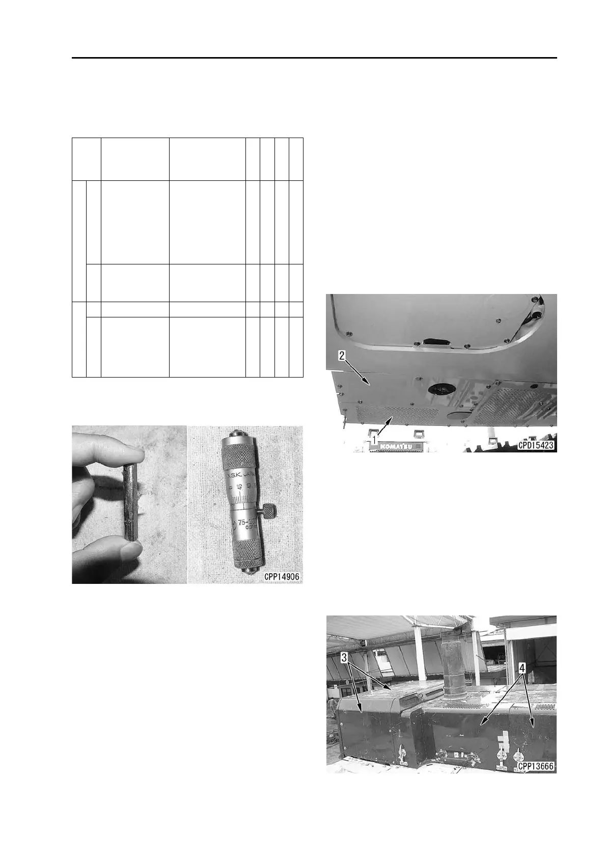
4. Remove 3 covers (3).
a Remove the covers on the rear side, too.
5. Open engine hood (4).
a Open the rear side, too.
Symbol
Part number Part name
Necessity
Q’ty
N/R
Sketch
B
2
Commercially
available
Pin gauge
Pin (7.50 mm
diameter
× 6.30
mm notch height)
for the bore of
module of 3.75
mm
t 2N
3
Commercially
available
Micrometer for
the bore
(75 – 100 mm)
t 1N
S
1 796-770-1301 Oil stopper q 1
2
Commercially
available
Pin gauge
Pin (6.75 mm
diameter) for the
bore of module of
3.75 mm
t 2N

 Loading...