PC800, 850-8 25
30 Testing and adjusting SEN00912-02
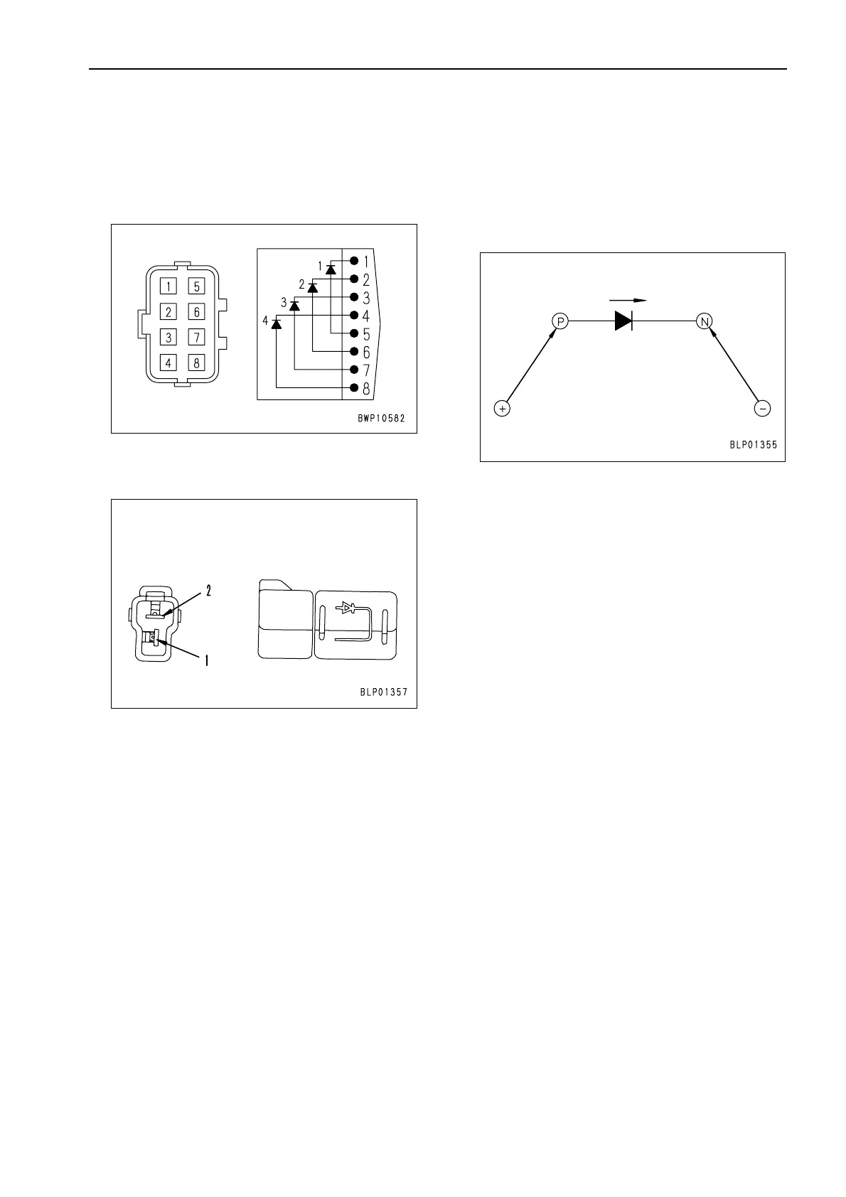
Inspection procedures for diode
a Check an assembled-type diode (8 pins) and
single diode (2 pins) in the following manner.
a The continuity direction of an assembled-type
diode is as shown in the diagram below.
a The continuity direction of a single diode is
shown on the diode surface.
1. When using digital type circuit tester
1) Switch the testing mode to diode range and
confirm the indicated value.
a Voltage of the battery inside is displayed
with conventional circuit testers.
2) Put the red probe (+) of the test lead to the
anode (P) and the black probe (–) to the
cathode (N) of diode, and confirm the dis-
played value.
3) Determine if a specific diode is good or no
good with the indicated value.
• No change in the indicated value: No
continuity (defective).
• Change in the indicated value: Continui-
ty established (normal) (Note)
Note: A silicon diode shows a value between
400 and 600.
2. When using analog type circuit tester
1) Switch the testing mode to resistance range.
2) Check the needle swing in case of the fol-
lowing connections.
i) Put the red probe (+) of the test lead to
the anode (P) and the black probe (–) to
the cathode (N) of diode.
ii) Put the red probe (+) of the test lead to
the cathode (N) and the black probe (–)
to the anode (P) of diode.
3) Determine if a specific diode is good or no
good by the way the needle swings.
• If the needle does not swing in Case i),
but swings in Case ii): Normal (but the
breadth of swing (i.e. resistance value)
will differ depending on a circuit tester
type or a selected measurement range)
• If the needle swings in either case of i)
and ii): Defective (short-circuited inter-
nally)
• If the needle does not swing in any case
of i) and ii): Defective (short-circuited in-
ternally)

 Loading...