mITX-DNV - User Guide, Rev. 1.0
www.kontron.com
// 22
4/ Connector Locations
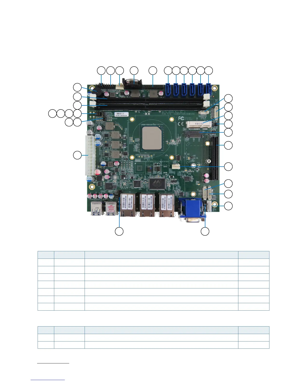
4.1. Top Side
Figure 2: Top Side
Table 8: Jumper List
Item Designation Description See Chapter
1 JP1 mPCIE / mSATA Selection for MPCIE1 7.16.1
2 JP2 USB Power Selection 7.16.2
3 JP3 AT / ATX Power Mode Selection 7.16.3
4 JP5 MFG Mode Selection 7.16.4
5 JP10 Clear CMOS Selection 7.16.5
6 JP11 Flash Security Override Selection 7.16.6
7 JP15 Power Output Selection for COM1 Pin-9 7.16.7
Table 9: Top Side Internal Connector Pin Assignment
Item Designation Description See Chapter
8 ATX1 2x12-Pin ATX Power Input Wafer 7.1
9 FAN1 CPU FAN Wafer 7.2
8
32