mITX-DNV - User Guide, Rev. 1.0
www.kontron.com
// 53
7.16. Switches and Jumpers
The product has several jumpers which must be properly configured to ensure correct operation.
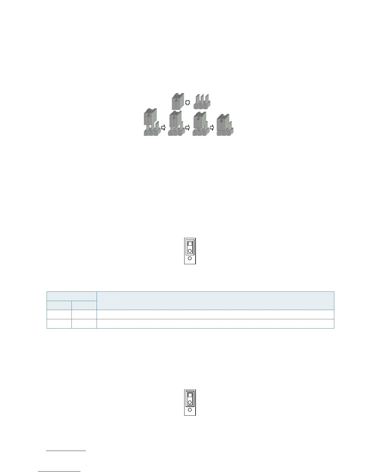
Figure 28: Jumper Connector
For a three-pin jumper (see Figure 25), the jumper setting is designated “1-2” when the jumper connects pins 1 and 2.
The jumper setting is designated “2-3” when pins 2 and 3 are connected and so on. You will see that one of the lines
surrounding a jumper pin is thick, which indicates pin No.1.
To move a jumper from one position to another, use needle-nose pliers or tweezers to pull the pin cap off the pins
and move it to the desired position.
7.16.1. mPCIe / mSATA Selection for MPCIE1 (JP1)
Figure 29: mPCIe / mSATA Selection JP1
Table 42: Pin Assignment JP1
Jumper Position
Description
Pin 1-2 Pin 2-3
X - mPCIe
- X mSATA
“X” = Jumper set (short) and “-” = jumper not set (open)
7.16.2. USB Power Selection (JP2)
Figure 30: USB Power Selection JP2
Table 43: Pin Assignment JP2