mITX-DNV - User Guide, Rev. 1.0
www.kontron.com
// 54
Jumper Position
Description
Pin 1-2 Pin 2-3
X - +5V
- X +5VSB
“X” = Jumper set (short) and “-” = jumper not set (open)
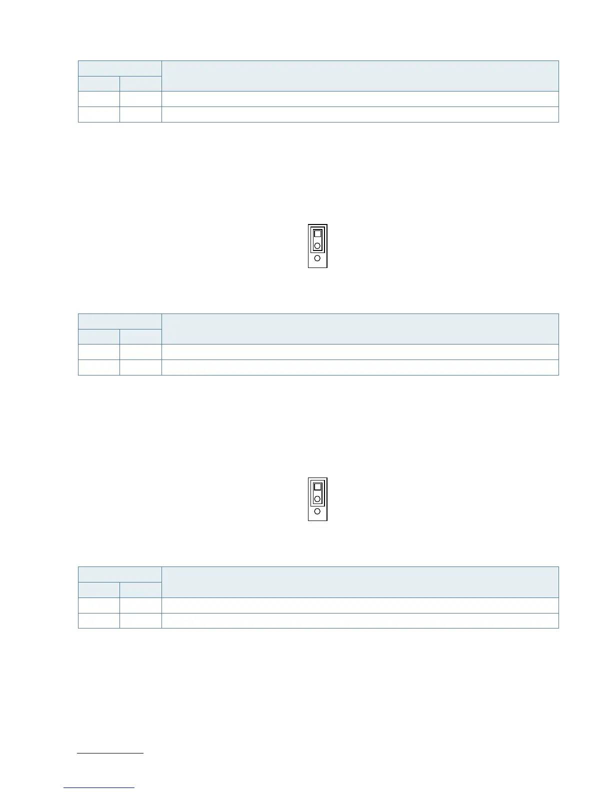
7.16.3. AT / ATX Power Mode Selection (JP3)
Figure 31: AT / ATX Power Mode Selection JP3
Table 44: Pin Assignment JP3
Jumper Position
Description
Pin 1-2 Pin 2-3
X - ATX Power Mode
- X AT Power Mode
“X” = Jumper set (short) and “-” = jumper not set (open)
7.16.4. MFG Mode Selection (JP5)
Figure 32: MFG Mode Selection JP5
Table 45: Pin Assignment JP5
Jumper Position
Description
Pin 1-2 Pin 2-3
X - Normal
- X Enable MFG Mode
“X” = Jumper set (short) and “-” = jumper not set (open)
7.16.5. Clear CMOS Selection (JP10)
Figure 33: Clear CMOS Selection JP10