22
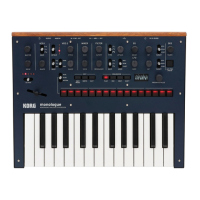
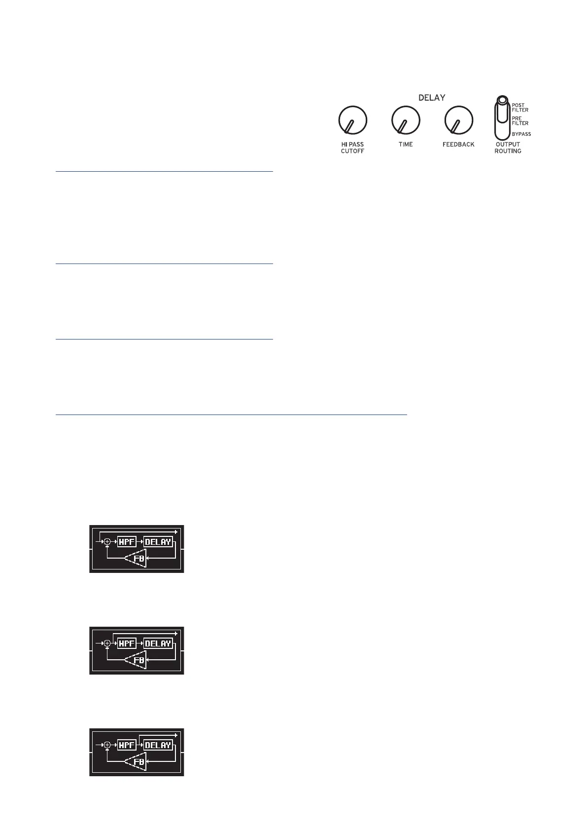
DELAY
The Delay eect is combined with a High
Pass lter. This allows you to create a wide
range of sounds.
HI PASS CUTOFF knob [0...1023]
Adjusts the cuto frequency of the high-pass lter. Sounds and harmonic com-
ponents below the HI-PASS CUTOFF frequency will be aenuated.
Turning the knob to the right will increase the cuto frequency.
TIME knob [0...1023]
This knob species the delay time.
Turning the knob to the right will make the delay time longer.
FEEDBACK knob [0...1023]
The Feedback knobs controls the regeneration of the Delay eect.
Turning the knob to the right will increase the amount of feedback.
OUTPUT ROUTING switch [BYPASS, PRE FILTER, POST FILTER]
Using this switch, you can specify where in the signal chain the Delay eect is
being applied.
The circuit routing is shown below. Also, refer to the block diagram (“Block
Diagram”, p. 3).
BYPASS: In this mode, the Delay and Hi Pass Filter are bypassed, and no eect
is applied to the sound.
PRE FILTER: The original sound is output before the Hi Pass Filter, and the Hi
Pass Filter is applied only to the delayed sound.
POST FILTER: This Hi Pass Filter is applied to both the original (dry) sound,
and the delayed sound.
 Loading...