Configuring a Digital Out Trigger Type
To configure a digital output trigger type:
1. On the GPIO Ports Settings page, select Digital OUT from the Trigger type option box
(Figure 10
).
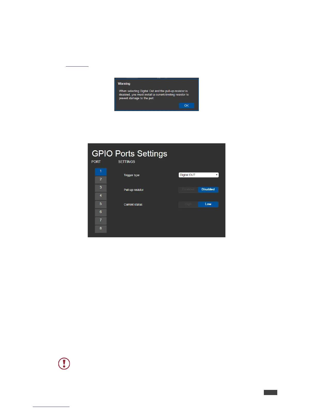
A Warning message appears.
Figure 11: Digital Out Selection Warning
2. Click OK.
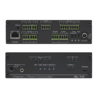
The Digital OUT options appear.
Figure 12: GPIO Ports Settings Page – Digital OUT Trigger Type
3. Select one of the following for the Pull-up resistor setting:
• Pullup resistor enabled:
The port can be used for controlling devices that accept a TTL signal such as for
powering LEDs. The voltage output is TTL positive logic: open: ~ 3.5V; closed: ~
0.3V.
When the pull-up resistor is enabled, the port state is high. For the state to be low,
you must click Low for the Current Status.
• Pullup resistor disabled:
The port is used for controlling external devices such as room or light switches. The
external source device determines the voltage output; the maximum voltage is 30V
DC and the maximum current is 100mA.
When the pull-up resistor is disabled, the port state is low and to set it high, you must
click High for the Current Status.