TP-590Rxr – Defining the TP-590Rxr HDMI Line Receiver
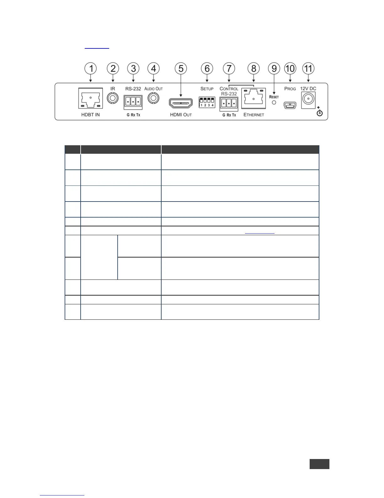
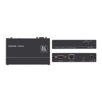
Figure 2 defines the rear panel of the TP-590Rxr.
Figure 2: TP-590Rxr Rear Panel
Connect to the HDBT OUT RJ-45 connector on the
HDBT transmitter
IR 3.5mm Mini Jack
Connector
Connect to an external infrared transmitter or sensor
RS-232 3-pin Terminal
Block
Connect to an RS-232 device to be controlled, (for
example, a projector)
AUDIO OUT 3.5mm Mini
Jack Connector
Connect to the stereo, analog audio acceptor
Connect to the HDMI acceptor
Sets the device behavior, (see Section 7.1)
RS-232 3-pin
Terminal
Block
Connect to the serial controller for this device
Connect to the Ethernet controller to control this device or
to a LAN to pass network traffic
Press and hold while power-cycling the device to reset to
factory default parameters
Connect to a PC to perform firmware upgrades
Connect to the supplier power adapter if power is not
supplied from a PoE device via the TP cable