CPK
3.1.2.4 Packing the Stuffing Box
Caution :
The pump is despatched from our Works with the stuffing box
packed.
Before repacking, thoroughly clean stuffing box gland (452),
packing compartment and shaft protection sleeve (524).
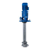
Cut the packing rings to correct length and ends at 45º. Ensure
that the packing rings ends come into contact with one another
on fitment. (See Fig. 7)
If the packing rings are either too long or too short, the stuffing
box will not be able to perform its function properly. In the case
of asbestos-graphite packing material, the rubbing faces of
the individual rings should be lightly coated with Molykote
before insertion in the packing compartment. The first packing
ring is then inserted and pushed home into the compartment
with aid of the stuffing box gland (452).
The following packing rings are then inserted into the packing
compartment one by one, making sure that the butt joint of
each ring is offset by 90
0
approx. in relation to the butt joint of
the preceding ring. The individual rings are pushed home
into the packing compartment with the aid of the stuffing box
gland (452). The packing rings should only be pressed lightly
against one another. They should be inserted in the packing
compartment in such a way that a clear gap of 6 to 8 mm is left
at the outer end of the compartment for the positive guidance
of the stuffing box gland (452).
The inserted packing rings should then be compressed
moderately with the aid of the stuffing box gland (452) and the
nuts (920.03). Then the nuts (920.03) should be slackened
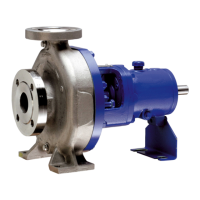
P 25/62 5 6 8
P 35/80 6 8 9
P 45/120 9 11 12
P 55/140 12 14 15
P 65/160s 15 17 18
Quantity of cooling water in LPM
Temperature of pumping liquid
Up to 150
0
C 150
0
to 250
0
C above 250
0
C
Bearing
Bracket
Fig. 7 : Cutting the packing rings to length.
Procedure
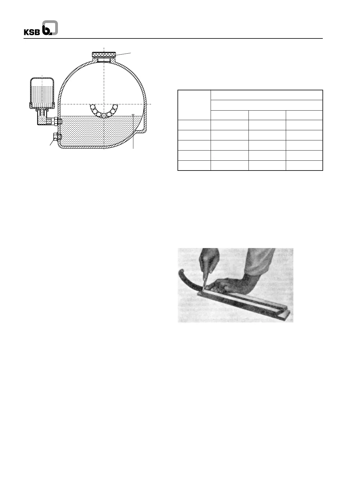
Unscrew vent plug. Pour in oil through the vent plug aperture
after removing the reservoir of the constant level oiler, until oil
appears in the vertical portion of the connection elbow of the
constant level oiler (see fig. 6).
Then fill the reservoir of the constant level oiler with oil and fit
it back into operating position. Screw vent plug in again. After
a short time has elapsed, check whether the oil level in the
reservoir has sunk. The reservoir should always remain filled.
If the vent plug is inaccessible or difficult to reach e.g. the oil
can be filled into the bearing bracket through the connection
elbow of the constant level oiler.
Caution :
The oil level should always be situated below the level of the
vent slot arranged at the top edge of the connection elbow
and this slot should always be perfectly dry. Do not tighten the
elbow by applying force on the reservoir use lock nut for this
purpose.
3.1.2.1. Stuffing Box
The shaft is sealed at its exit through the casing by soft packed
stuffing box or a mechanical seal. Change over from gland
packing execution and vice verca is possible by using
conversion kit. For details refer KSB.
3.1.2.2 Shaft Seal
Soft-packed stuffing box reduce the flow of leakage liquid at
the clearance gap between casing cover and shaft protection
sleeve when the pressure inside the pump is higher than
atmospheric. Conversely, on pumps which operate on suction
lift pressure, the soft-packed stuffing box prevents the ingress
of air into the pump. Sealing is effected by means of soft
packings arranged in a number of rings in the annular space
between the casing cover (161) and the shaft protection sleeve
(524) and lightly compressed by the stuffing box gland (452).
Refer Fig. 8.
3.1.2.3 Cooling of Casing Cover
The casing cover jacket of soft packed stuffing boxes must be
cooled if the temperature of pumped fluid exceeds 90
0
C.
Clean, clear and non aggressive water is recommended for
Fig. 6 : Oil fill
Oil level in bearing
bracket and connection elbow
Drain
plug
Vent or filler
plug
cooling (pH =
~
7). The maximum pressure of cooling water is
10 bar. The cooling water quantities are specified in lpm for
∆t = 15
0
C in Table No. 1.
Inlet temp. : 10
0
C to 30
0
C
Outlet temp. : 45
0
C max.
3