CPK
Annexure II : Metallic washer fitment for impeller, impeller nut and shaft protection sleeve
(wherever applicable)
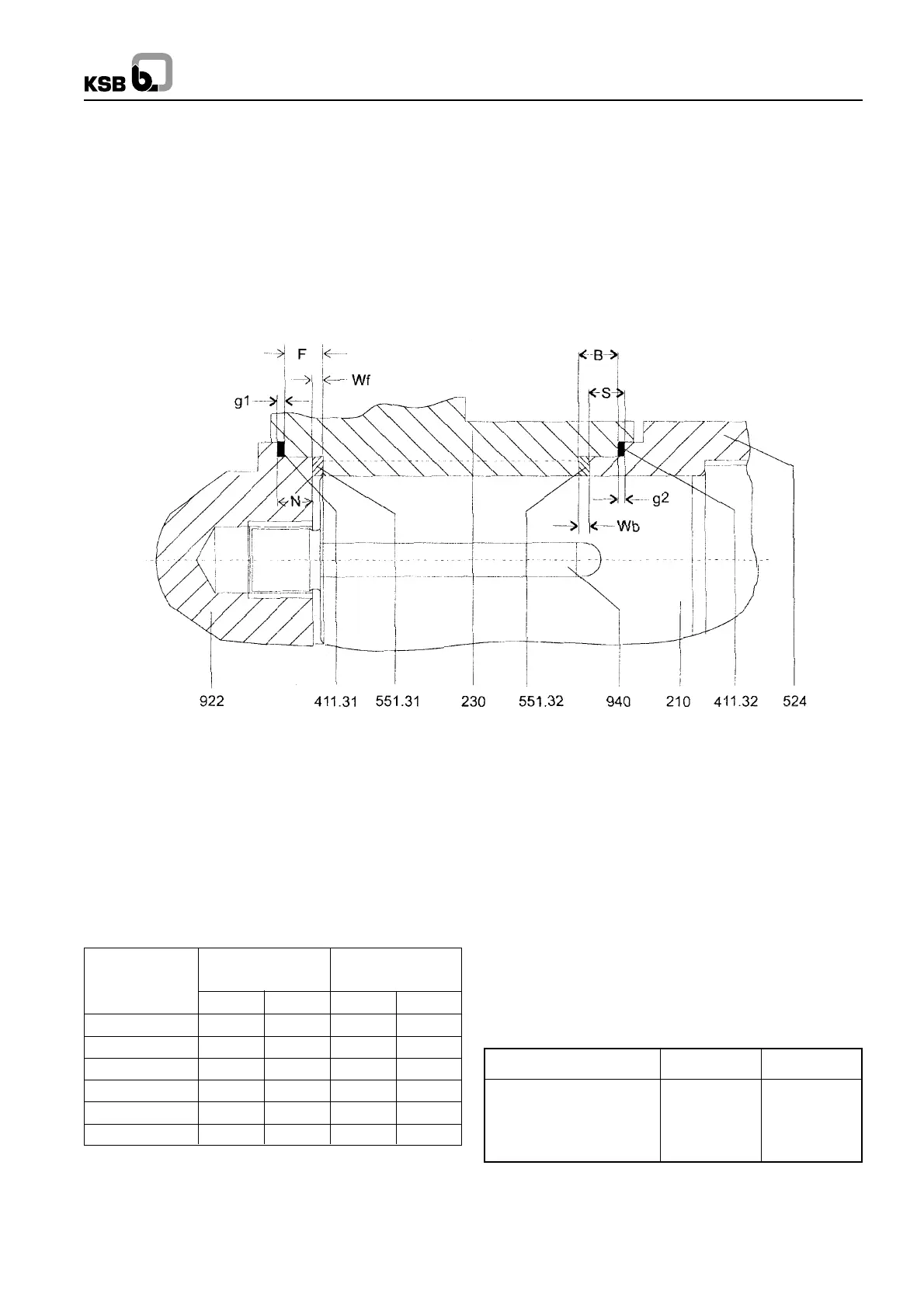
Metal to metal fit of impeller nut (922), impeller (230) and shaft protection sleeve (524) against the shaft shoulder is done as
shown in the sketch and as described in the procedure given below :
This is achieved without reworking of standard parts. However recheck cavity dimensions as shown below and rework only if
required.
Procedure
Spacer washer (551.32) and gasket (411.32) are inserted between shaft protection sleeve (524) and impeller (230). Then the
spacer washer (551.31) and gasket (411.31) are placed between the impeller (230) and impeller nut (922) and finally impeller
nut (922) is tightened.
Part No. Part Name
210 Shaft
230 Impeller
411.31/32 Graphite gaskets
524 Shaft protection sleeve
551.31/32 Spacer washers
922 Impeller nut
940 Key
Note :
1. When bearing brackets P 55/140s & above; are used,
check if the washer 551.31 rests on the supporting face of
the impeller. If not, rework length of the key.
2. For bearing brackets P 55/140s & above; part no. 551.32
will be in two halves.
Annexure III : Wearing Ring Clearances
The clearances are in mm and identical on the suction & dis-
charge side.
* For all CPK C pumps and for CPK E pumps with
temperature > 280
0
C.
To calculate g1 & g2 use following formula
1. g1 + F = N + Wf
2. g2 + B = S + Wb
Where wf : front washer thickness
wb : back washer thickness
g1 : front gasket cavity thickness
g2 : back gasket cavity thickness
F : Impeller front length
B : Impeller back length
S : Sleeve length
16
Pump size Group 1 Group 3*
up to DN 65 0.4
+ 0.1
0.6
+ 0.1
DN 80-150 0.5
+ 0.1
0.65
+ 0.1
DN 250 & above 0.65
+ 0.15
0.75
+ 0.15
DN 200 0.55
+ 0.1
0.65
+ 0.15
Washer thickness Gasket thickness
(mm) (mm)
Bearing
Bracket
551.31 551.32 411.31 411.32
P 25/62 1.1 1 1.5 1.5
P 35/80s 2.1 1 1.5 1.5
P 45/120s 2.1 1 1.5 1.5
P 55/140s 2.1 1 1.5 1.5
P 65/160s 3.1 1 1.5 1.5
P 80/200s 5 1 1.5 1.5
 Loading...