CPK
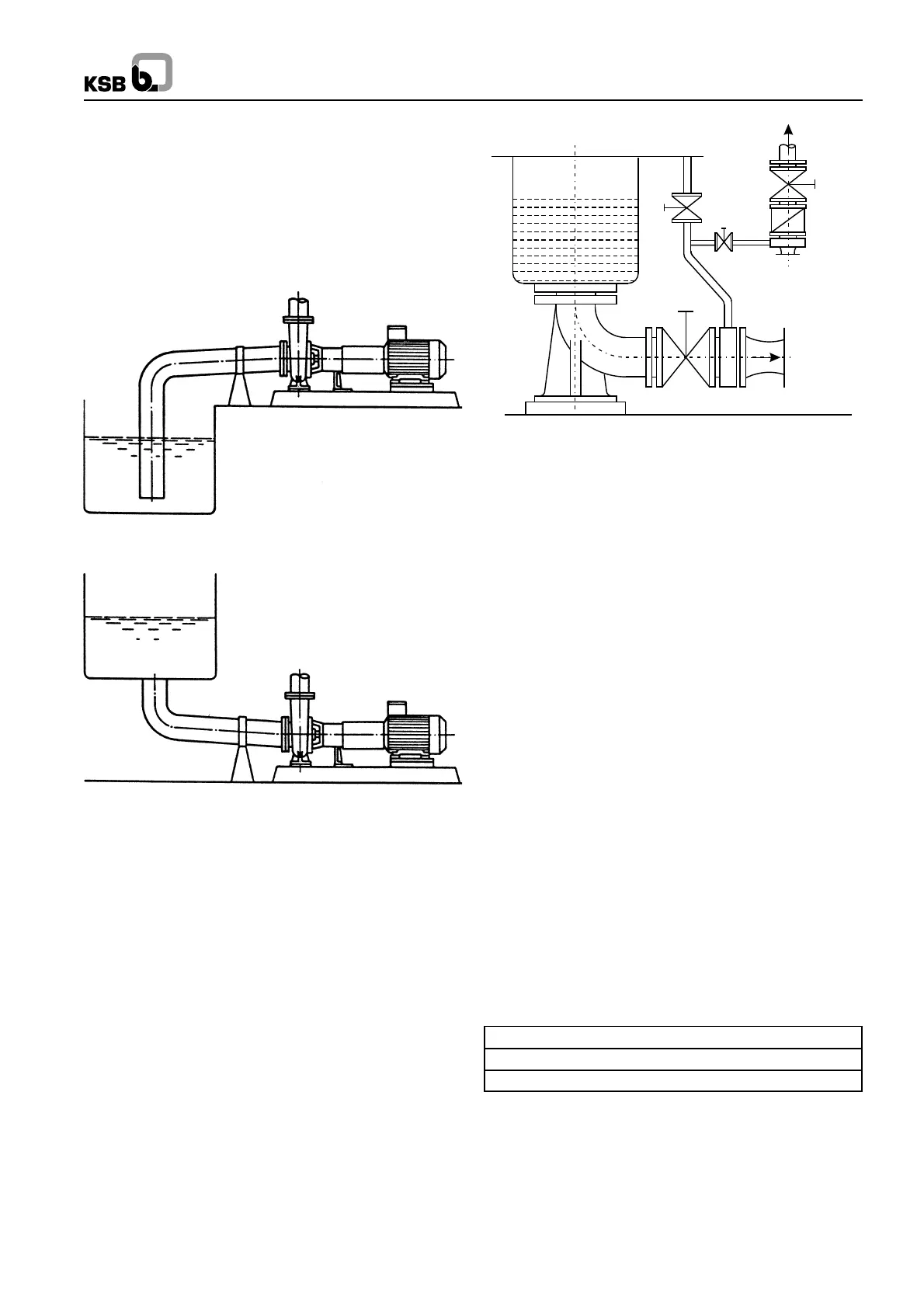
pipelines should be at least equal to the nominal sizes of the
pump nozzle. In case the suction pipeline size is bigger, the
connection should be done by means of an eccentric reducer,
in order to avoid air pockets. We recommended the
incorporation of check valves or non return valves and
isolating valves in the system, depending on the type of
installation and pump. Any thermal expansion of the piping
(due to high temperatures) must be compensated by suitable
means, so as not to impose any additional load on the pump.
2
Fig. 3
Fig. 4
2.4.1 Auxiliary Connections
The auxiliary connections required for your pump (cooling,
heating, sealing liquid, flushing liquid etc. as the case may
be) are indicated in the installation drawing and on the piping
diagram in respect of size and location.
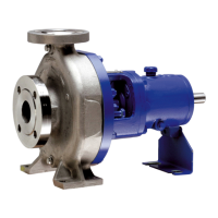
2.4.2 Vacuum Balance Line
If the pump has to pump a liquid out of a vessel under vacuum,
it is advisable to install a vacuum balance line. This line should
have a nominal size of 25 mm at least. It should be arranged
to lead back into the vacuum vessel at a point above the
highest permissible liquid level. An additional line starting at
the pump discharge nozzle facilitates venting of the pump
before start up. The vacuum-tight isolating valve E in this
connecting line should be closed after the venting procedure
& should remain closed while the pump is running. The main
isolating valve C in the vacuum balance line must remain
open at all times when the pump is running and should be
closed when the pump is shutdown. Refer Fig. 5.
2.5 Coupling Guard
In compliance with the accident prevention regulations, the
pump may only be operated if it is fitted with a coupling guard.
If the customer states specifically that coupling guard is not to
be supplied by KSB, it must be provided by the pump operator.
2.6 Measuring Instruments
Each pump should be equipped with two pressure gauges,
one at the suction nozzle and the other at the discharge nozzle.
Their measuring range should be suitable for the prevalent
pressure conditions, and they should be provided with a stop
cock or stop valve. If the suction conditions demand (e.g.
suction lift operation), the gauge on the suction nozzle should
be pressure vacuum gauge.
2.7 Final check
Check the alignment once more as described in section 2.3. It
must be possible to rotate the pump rotor freely without
additional effort by hand at the coupling.
3. Commissioning, Start-up/Shutdown
3.1 Preliminary remarks regarding commissioning
3.1.1 Lubricants
The bearing bracket should be filled with oil of any one of the
following types and specifications :
A Main isolating valve R Check valve
B Vacuum balance line V Vessel under vacuum
C Isolating valve Z Intermediate flange
E Vacuum-tight isolating valve
Fig. 5 Suction line and vacuum balance line
Indian Oil : Servosystem 46
Hindustan Petroleum : Enklo 46
Bharat Petroleum : Bharat Hydrol 46
If some other make of oil is used the properties of the oil should
be as follows.
Kinematic viscosity : 46 +4mm
2
/s at 40
0
C
Flash point : +175
0
C
Solidification point : 15
0
C
Applicable temperature : Higher than permissible bearing
temperature
for 10
0
C contact KSB