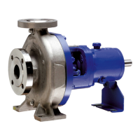
CPK
4.2.3 Procedure
Unscrew oil drain plug beneath the constant level oiler and
drain off the old oil. When the bearing bracket is empty, replace
the oil drain plug and fill in fresh oil in accordance with
section 3.1.1.
4.3 Preservation
If the pump is taken out of service for a prolonged period, it is
advisable to dismantle it completely. Proceed as described
in section 5.2 “Dismantling”. All components should be
thoroughly cleaned, dried and all bright components coated
with grease. Thereafter the pump should be reassembled.
All apertures on the pump should be plugged with wooden
cover plates fitted with O rings. A sachet filled with silicagel
(silicagel absorbs moisture) should be attached to the inside
faces of the oil soaked wooden cover plates on the suction
and discharge nozzles (i.e. inside the nozzles).
The packing should be removed from the stuffing box
compartment and it should be sealed by oil-soaked wooden
half tubes, each provided with two O-rings, in order to prevent
flexible coupling elements in the course of time, these element
should be replaced by new ones in good time. Otherwise
unbalance vibration will increase leading to failure of coupling.
It is necessary to maintain a log book on hourly basis, where
the suction and discharge pressure, flow rate, bearing
temperatures (pump end and motor end), motor current and
voltage should be noted.
4.2 Bearings and lubrication
4.2.1 Lubricant quantities
The anti-friction bearings are oil lubricated; Required lubricant
fills for different. brg. bkts are as under :-
4.2.2 Oil change
The first oil change should be carried out after 300 hours of
operation approx. and subsequent oil changes once every
3000 hours of operation approx. In case of newly replaced
bearings, the oil should be changed after 200 hours of running
and thereafter every 1000 working hours.
Heavy duty bearing assembly
Table No. 2 Arrangement of bearings & quantity of oil.
Standard Bearing Assembly
Bearing Deep groove ball bearings Oil fill in
bracket 321.01/02 DIN 625/C3 bearing litres
clearance
P25/65 6305 C3 0.2
P35/80 6307 C3 0.5
P45/120 6409 C3 0.5
P55/140 6411 C3 1.5
Bearing Cylindrical roller Angular contact Oil fill
Bracket bearing 322 ball bearing 320 in litres
P25/62s NU305 C3 7206BG 0.2
P35/80s NU307 C3 7307BG 0.5
P45/120s NU311 C3 7311B.TVP.UA80 0.5
P55/140s NU313 C3 7313B.TVP.UA80 1.5
P65/160s NU413 7315B.TVP.UA80 1.8
the penetration of moisture (not applicable to pumps fitted
with mechanical seals).
Caution :
Use acid free oils and greases only, when preserving the
pump.
5 Special Instructions
5.1 General Precautions
Before commencing dismantling .
Make sure that the pump will not be accidentally switched on.
The isolating valves in the suction and discharge line must be
closed.
The volute casing must have cooled down to ambient
temperature. The volute casing must be drained and
pressureless.
Always refer to the relevant sectional drawing when
dismantling and reassembling the pump.
5.2 Dismantling
5.2.1 Soft-packed stuffing box
Refer fig. 8.
1. Drain the oil in accordance with section 3.1.1.
2. Remove the coupling guard.
3. Disconnect coupling spacer, or if no spacer is fitted
remove the driver.
4. Disconnect and remove the auxiliary connections on
your pump.
5. Loop a rope tightly around the top stay of brg bkt. lantern.
6. Unscrew hex head bolt (901.02) and the base frame
fixing bolts of support foot (183) and remove the support
foot.
7. Unscrew hex nuts (920.01) and pull the complete
bearing bracket together with casing cover, shaft,
impeller and bearing bracket lantern out of the volute
casing. Use jack bolts for assistance in doing this having
first cleaned the threads. Take care not to damage
gasket (411.03).
8. Unscrew impeller nut (922) with its Heli-coil insert (right
handed screw thread), remove gasket (411.31) and
washer (551.13), pull off impeller (230), remove key
(940.01).
9. Remove stuffing box gland (452) together with stuffing
box pressure ring (454) after having unscrewed hex
nuts (920.02).
10. Remove Casing cover 161 remove gaskets (411.10) &
O-ring (412.01). Next remove stuffing box packing 461
& lantern ring (458). Then remove neck ring after
unscrewing screws (900).
11. Pull shaft protection sleeve (524) together with gasket
(411.32) & washer (551.32) and splash ring (507) off
the shaft.
12. Unscrew hex nuts (920.02) and remove bearing
bracket lantern, (344).
13. After having unscrewed allen head screw in the
coupling hub, pull the coupling half of the pump shaft
5