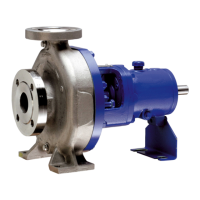
CPK
Caution :
1. For heavy duty bearing bracket, the antifriction bearings
320 must be mounted in O-arrangements (see sectional
drawing) Remember the spacer rings 504.01/02 for
normal/heavy brg bkts.
2. When the bearings 320 have been mounted, the
bearing nut 923 without the lock washer 931, must be
screwed on firmly with the aid of a hook spanner. (Do
not use a hammer).
3. The bearing nut must be removed again, the lock
washer inserted and the bearing nut screwed on firmly
again with the hook spanner (Do not use a hammer).
Bend lock washer forward to lock the nut.
4. Take care not to damage the oil seal rings 421.01/02
(when applicable) when mounting bearing covers
360.01/02.
5. The impeller nut should be tightened firmly. The
impeller nut should be tightened a new some 20 to 30
minutes after the initial tightening. Refer Annexure II
for details of metallic washer fitment in impeller.
6. After assembly into the volute casing which has
remained in situ in the piping the coupling alignment
should be checked (see section 2.3).
7. Fill in oil in accordance with section 3.1.1.
5.3.1 Reassembly of stuffing box packing
Assembly recommendations (when pump is dismantled)
Clamp casing cover 161 in a vice, or keep it on an assembly
table and slip in neck ring 456. Then insert the first packing
ring with its butt joint lying in the horizontal plane.
Hold the packing ring tight and slip the shaft protection sleeve
into the packing compartment from the pump end, chamfered
end first. Open out the internal diameter of the packing ring
slightly with the aid of the shaft protection sleeve by sliding
the latter to and fro. Then pull out the shaft protection sleeve
and insert the second packing ring with its butt joint offset 90
0
in relation to the butt joint of the first packing ring. Repeat the
opening out process with aid of the shaft protection sleeve.
Then insert lantern ring 458 (if fitted to your pump). Then insert
the remaining packing rings in succession with their butt joints
offset, and repeating the opening out process for each ring.
When the last packing ring has been inserted the shaft
protection sleeve should be left in the packing compartment.
Insert stuffing box ring 454 in such a way that its joint face is at
right angles to the stuffing box gland. Slip stuffing box gland
452 and tighten it lightly only by hand, by means of two hex
nuts 920.02.
Mount the completely packed casing cover together with the
shaft protection sleeve into the pump.
Caution :
The stuffing box should drip slightly when the pump is running.
Any sealing and cooling liquid connections which are in use
must be checked in respect of unimpeded fluid flow from time
to time.
When the stuffing box gland has been tightened repeatedly
(during use) until it abuts, it is time to repack the pump
completely with new packing.
6
with the aid of an extractor device and remove key
(940.02).
14. After having unscrewed Allen head screws (914.01/
02) in coupling hub dismantle bearing covers 360.01
and 360.02 at pump and drive ends together with flat
gaskets (400.01/02), oil seals (421.01/02) / Lantern
rings (423.01/02) as applicable.
14.1 Standard bearing assembly :
14.1.1 Carefully remove the shaft (210) together with deep
groov ball bearing (321.02) out of the bearing bracket.
14.1.2 Heat up the deep groove ball bearings and pull them
off the shaft.
14.2 Heavy duty bearing assembly :
14.2.1 Carefully remove the shaft (210) together with angular
contact ball bearings (320) and inner race of cyl. roller
bearing (322) towards the drive end of the pump.
14.2.3 Remove roller cage of cyl roller brg (322) from the
bearing bracket. Then remove spacer ring (504.2) &
circlip.
14.2.4 Bend back lock washer (931); unscrew bearing nut
(923) (righthanded screw thread) remove lock washer.
14.2.5 Heat up angular contact ball bearings (320) and the
inner race of cylindrical roller bearing (322) and pull
them off the shaft. Remove spacer ring (504.01) (applies
only to bearing bracket size 25/62s).
14.2.6 Clean all the components and examine them for signs
of wear. Touch up the damaged components or replace
them by new ones, if necessary.
5.2.2 Mechanical seal stuffing box :
1. Unscrew hex nuts (920.2) and pushback mechanical
seal cover (471) until it abuts against splash ring (507).
2. Dismantle casing cover 161 together with O - ring 412.1
3. Pull the complete mechanical seal together with shaft
protection sleeve 524, mechanical seal cover 471, and
splash ring 507 off the shaft.
5.3 Reassembly
The pump should be reassembled in accordance with the
rules of sound engineering practice. The fits of individual
components should be coated with graphite or other suitable
lubricants before assembly and the same applies to screwed
connections.
O-rings and radial shaft seal rings should be examined for
signs of damage and replaced by new ones, if necessary.
Flat gasket should in principal be replaced by new ones and
make sure that the thickness of the new gasket is exactly the
same as that of the old one.
Reassembly proceeds in reverse sequence to dismantling.
The following points should be carefully observed.
Use only the bearing types and sizes specified in section
4.2.1. The antifriction bearings 320/321.01/02 and inner race
of antifriction bearing 322 (when applicable) should be
preheated in an oil bath to 80
0
C approx. before being slipped
on to the shaft until they abut against the shaft shoulder.