CPK
1. General
Your centrifugal pumps will give you completely trouble free
and satisfactory service on condition that it is installed with
due care and properly maintained. It is absolutely essential
that the instructions contained in this manual be scrupulously
observed and that the pumps are not operated under conditions
which differ from those specified under our ‘Operating
Conditions’. This operating instruction manual does not take
any account of any safety regulation which may apply to the
installation site, and the Site Engineer or Site Operator is
responsible for notifying our erection staff of any such
regulations and seeing that they are complied with.
The pump type size, main operating data and works order
number are stamped on the name plate affixed to the pump.
Please make sure to quote this information every time you
write to us in respect of queries, repeat orders and particularly
when ordering spare parts.
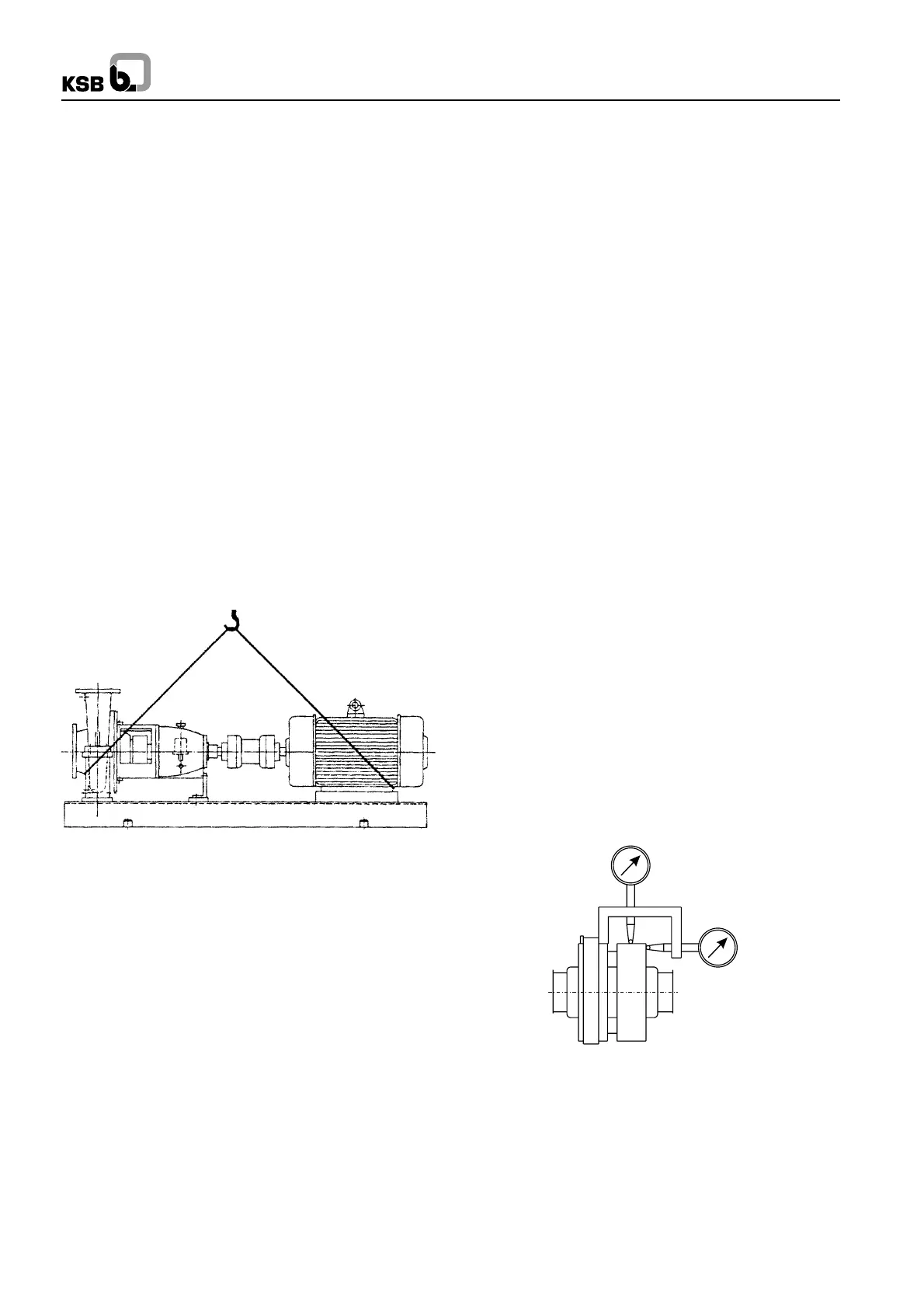
1.1 Handling
The Pump set should be properly handled and slung for
transport. Do not thread the ropes through the eye bolt on the
motor. (See Fig. 1)
During handling do not remove the rubber blankings provided
on the suction and discharge nozzles.
2. Installation (on site)
2.1 Foundation
Make sure that the concrete foundation has set firmly before
placing the base frame along with the pump set or pump on
it. The surface of the foundation should be truly horizontal and
perfectly flat. The foundation bolts should be suspended in
the baseplate.
2.2 Base Frame and Pump
Procedure
1. Bolt the Pump on the base frame.
2. Bolt the packer plates on the bottom pads of the base
frame, if applicable.
3. Place the unit on the foundation.
4. Suspend the foundation bolts in the pockets provided on
the foundation block.
5. Level the pump on the delivery flanges or feet within 0.2
mm per mtr., using jacking bolts provided on the corners
of the base frame.
Fig. 1 : Pump and driver mounted on a combined baseplate
2.4 Connecting the piping
Never use the pump itself as an anchor point for the piping.
Suction lift lines should be laid with a rising slope towards the
pump and suction head line with a downward slope towards
the pump. The pipelines should be anchored in close proximity
to the pump and should be connected to the latter without
transmitting any stress or strain, nor should the weight of the
piping be loaded on to the pump. The nominal sizes of the
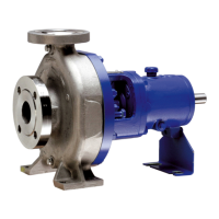
Fig. 2 : Alignment of coupling
6. Grout the foundation bolts and the packer plate (if
applicable) by using quick setting non-shrink cement,
ACC make “Shrinkkomp” or FORSORC make
“Conbextra-GP2” or equivalent.
7. Allow curing time of 24 to 72 hours depending upon the
grout used.
8. Remove bolts which are holding packer plates with the
base frame (if applicable).
9. Carry out final levelling by inserting shims (S.S. Shims
preferred) between packer plates and base frame (if
applicable).
10. Tighten the foundation bolts and recheck the levelling.
Correct it, if necessary.
11. Grout the complete base frame, including hollow portion,
if any, using conventional grouting mix i.e. portland
cement, sand and aggregate in proportion 1:2:4 and
gravel size not exceeding 20 mm.
12. Plaster the foundation and apply suitable oil resistant
paint.
For figures refer Annexure I.
2.3 Alignment of pump and driver
Accurate coupling alignment requires a coupling alignment
jig. This can be manufactured from 20 x 20 mm steel flat. The
jig should be attached to the shafts. See Fig. 2.
The coupling can be considered correctly aligned with the aid
of the jigs illustrated if the difference measured does not
exceed 0.1 mm both in the radial and axial directions,
measurements being taken in 4 planes at 90
0
intervals.
Alignment should be checked when the pump is hot
(applicable for pump handling hot fluids), In case any deviation
is found, please check the pipe lines and or realign the pump.
The coupling alignment check should be repeated after the
piping has been connected to the pump to ensure stress free
piping. Prior to alignment, individual concentricity of coupling
should be checked. It should be within 0.03 mm. If not,
corrective action should be taken. The coupling should be
dynamically balanced in accordance with VDI 2060 (ISO
1940)/G6.3 for motor driven pumps and G2.5 for turbine driven
pumps.
1