4 Description of the Pump (Set)
17 of 76
CTN / CTN-H
Refer to the data sheet for the relevant bearing bracket design.
4.5 Configuration and function
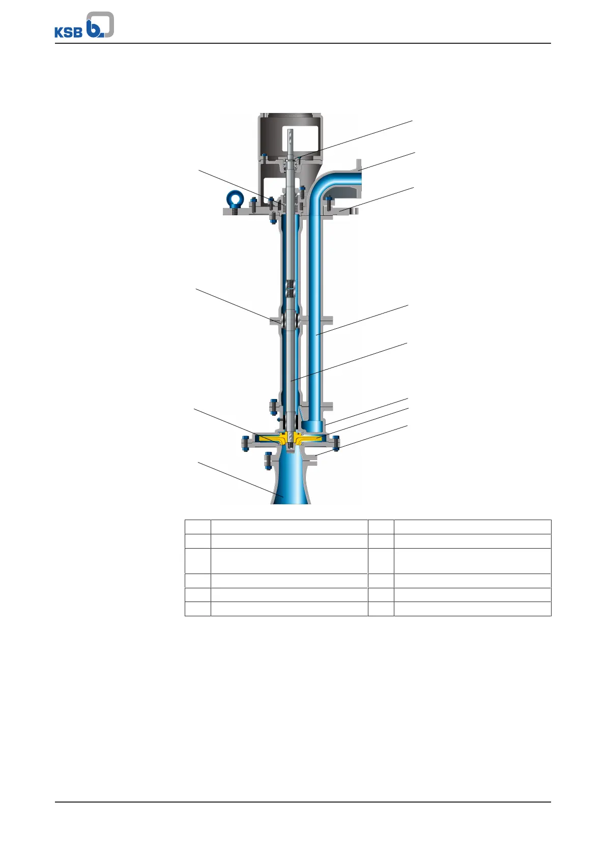
Fig.3: Sectional drawing
1 Shaft seal 2 Plain bearing
3 Clearance gap 4 Suction nozzle
5 Thrust bearing (rolling element
bearing)
6 Flanged bend
7 Soleplate 8 Pipe assembly
9 Shaft assembly 10 Volute casing
11 Impeller 12 Suction cover
Design Vertical submersible pump with one or two stages. Shaft seal is not in contact with
the fluid handled; pump is not self-priming.
Function The fluid enters the pump vertically via the suction nozzle (4) and is accelerated
outward by the rotating impeller (11). In the flow passage of the volute casing (10)
the kinetic energy of the fluid is converted into pressure energy. The fluid is pumped
through the pipe assembly (8) to the flanged bend (6), where it leaves the pump. The
clearance gap (3) prevents any fluid from flowing back from the casing to the suction
cover (12). At the rear side of the impeller, the shaft assembly (9) enters the volute
casing (10) which provides the boundary for the hydraulic system. The shaft passage
through the soleplate (7) is sealed to atmosphere with a shaft seal (1). Depending on
the installation depth, the shaft assembly (9) can either consist of a single shaft or