7 Servicing/Maintenance
55 of 76
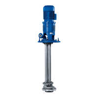
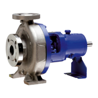
CTN / CTN-H
Adjusting the lubricator
NOTE
Refill the lubricator approx. every 8 days when working in eight-hour operating
periods.
1. Turn the counter nut (1) back by four turns.
2. Screw the upper section (2) in by four turns.
3. Tighten the counternut again (1).
NOTE
When the upper section is screwed into the lower section completely, the lubricator
is emptied.
7.5.6 Assembling thrust bearings
ü The notes and steps stated in (ðSection7.5.1,Page48) to
(ðSection7.5.5,Page52) have been observed/carried out.
ü All dismantled parts have been cleaned and checked for wear.
ü Any damaged or worn parts have been replaced by original spare parts.
ü The sealing surfaces have been cleaned.
1. Heat bearings 320.2 in the oil tank to approx. 80°C.
2. Slide bearings 320.2 onto the cleaned shaft and into bearing bracket lantern 344
until they abut against the spacer discs 550.21.
CTN with oil-lubricated
thrust bearings
ü The oil tube has been checked for unimpeded throughflow.
1. Slide the bearings onto cleaned centring sleeve 526.04.
2. Attach lockwasher 931.03.
3. Screw on slotted round nut 920.24, tighten and lock.
The cast notches in bearing bracket lantern 344 and in bearing cover 360 must
be located on top of each other.
Ensure the position of the recess in the gasket is such that the oil return grooves
can perform their function.
Adjusting the axial impeller clearance
CTN, CTN-H The impeller is centred in the volute casing, i.e. the axial distance between the
impeller and the suction cover or the impeller and the volute casing (for a single-
stage pump) or the stage casing (for a two-stage pump) is the same. To achieve this,
assemble the complete pump without angular contact ball bearing 320.02 and drive
lantern 341.
Push the shaft down until it will not go any further and measure dimension A
1
.
Determine the difference B = A
1
- C.
Push the shaft upwards until it will not go any further and measure dimension A
2
.
Determine the difference D = A
1
- A
2
.
The required thickness S of the spacer discs is calculated as follows:
S = B - D/2
Sizes Dimension C
25 / 40 / 50 37,5
80 / 100 / 125 / 150 53,0
200 / 250 69,0
1. Slide the set of spacer discs 550.21 onto the shaft as far as they can go in order
to ensure dimension S.
2. Mount angular contact ball bearings 320.02 with slotted round nut 920.21 and
lock washer 931.01.