7 Servicing/Maintenance
56 of 76
CTN / CTN-H
NOTE
Install angular contact ball bearings in face-to-face arrangement. Angular contact
ball bearings installed must always be from the same manufacturer.
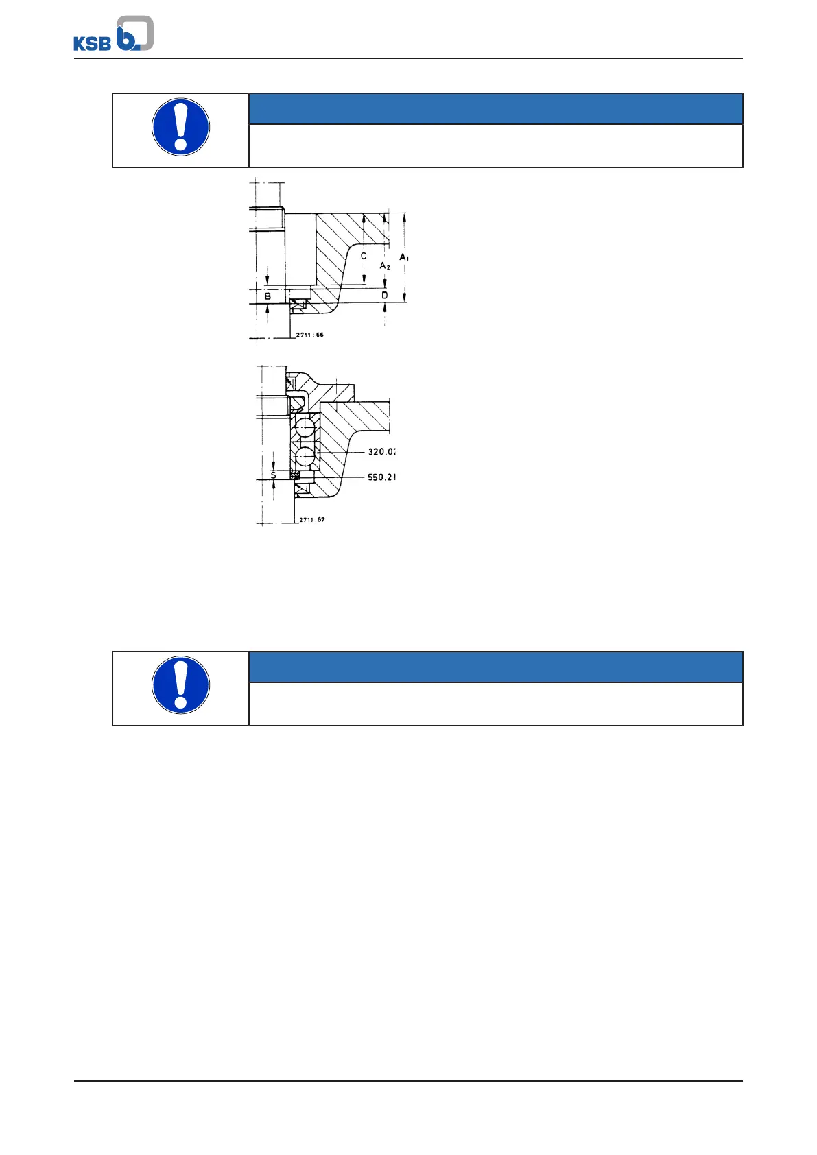
Fig.10: Determining spacer disc thickness S
Fig.11: Assembled thrust bearings with set of spacer discs
3. Carefully slide on bearing cover 360.02 with lip seal 421.04 and fasten.
Check that the rotor can easily be rotated by hand, without causing any
grinding noises.
4. Align the coupling. (ðSection5.3,Page20)
CTN with oil-lubricated
thrust bearings
NOTE
The overall axial clearance of the pump rotor is determined by lowering and pulling
the rotor up using the centring sleeve.
Adjusting pump sizes 25/40/50
1. Turn the centring sleeve to the left.
Move the rotor to the lower stop.
2. Measure the dimension of the upper edge of the centring sleeve/shaft end.
3. Turn the centring sleeve to the left.
Move the rotor to the upper stop.
4. Measure the dimension of the upper edge of the centring sleeve/shaft end.
5. Lower the rotor from the upper stop by 0.5x the overall clearance.
One full turn of the centring sleeve will cause the rotor to move upwards or
downwards by 1.5mm.
6. Secure the centring sleeve with key 940.02 to prevent rotation.
If the key cannot be pushed into the recess, turn the centring sleeve so that the
nearest recess aligns with the keyway.
Adjusting pump sizes 80/100/125/150/200/250
1. Turn bearing nut 923 to the left.
Move the rotor to the lower stop.
2. Measure the dimension of the upper edge of the bearing nut/shaft end.