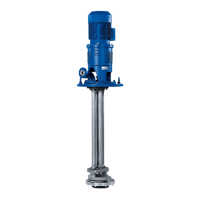
7 Servicing/Maintenance
50 of 76
CTN / CTN-H
WARNING
Hot surfaces due to heating of components for assembly/dismantling
Risk of burns!
▷ Wear heat-resistant protective gloves.
▷ Remove flammable substances from the danger zone.
1. Heat the bearing sleeve to approx. 200°C and slide quickly onto the shaft.
CAUTION
Improper reassembly
Damage to the plain bearing
▷ Always slide the guide ring with the marking (groove) onto the shaft first.
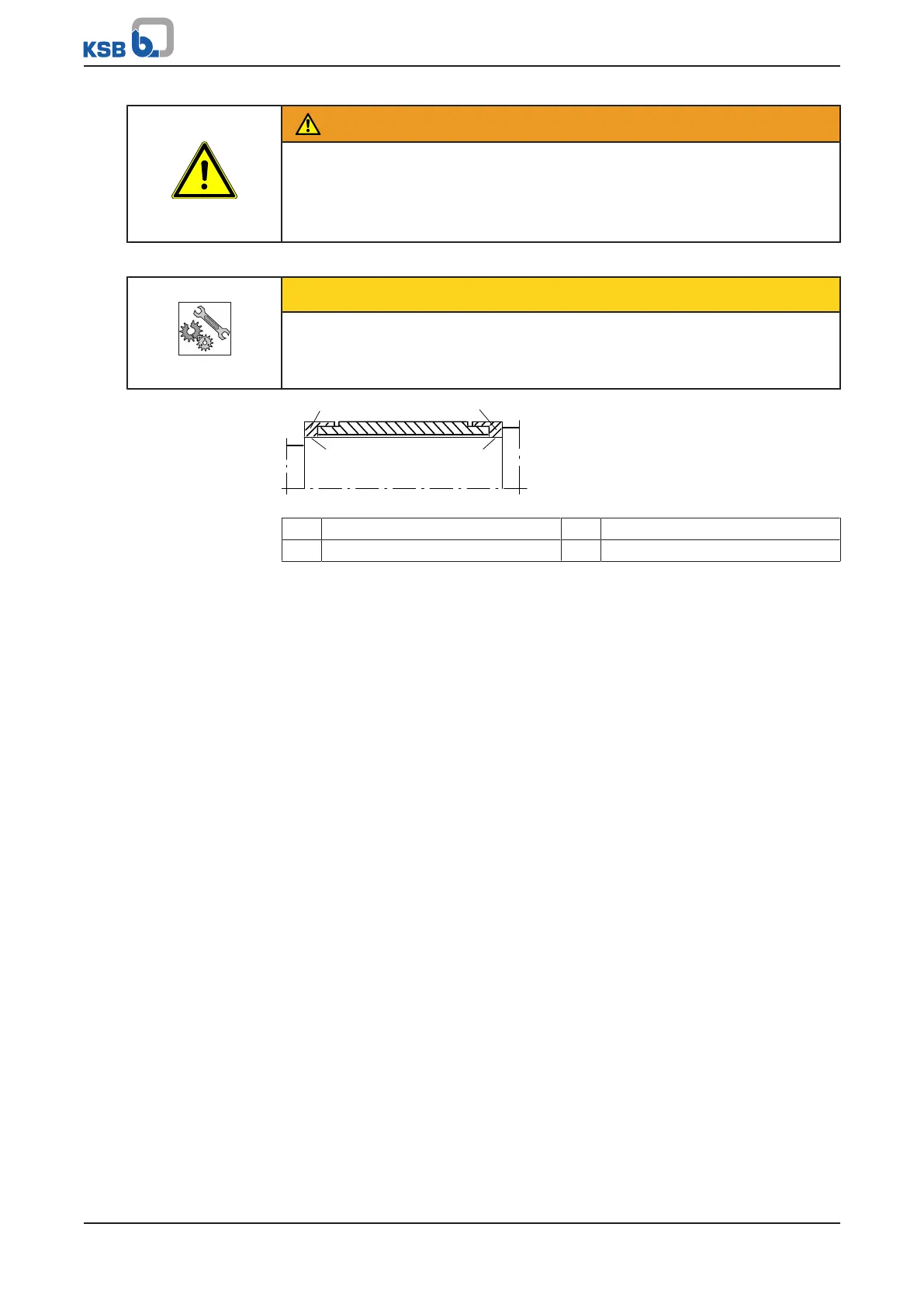
Fig.7: Sliding the bearing sleeve onto the shaft
1 Guide ring without marking 2 Press fit
3 Guide ring with marking 4 Clearance fit
C30EH, solid SiC Bearing sleeve made from brittle and wear-resistant materials, e.g. C30EH, solid SiC
(special design)
ü The individual parts have been placed in a clean and level assembly area.
ü All dismantled parts have been cleaned and checked for wear.
ü Any damaged or worn parts have been corrected or replaced with original spare
parts.
ü The sealing surfaces have been cleaned.
1. Slide the bearing sleeve onto the shaft and secure with grooved pin 561.18 or
hexagon head bolt 900.18.
2. CTN: The grooved pins 561.21/.22 must engage in the recess of the pipe
assembly when installing bearing housing 350.04.
CTN-H: The grooved pins 561.21/.22 must engage in the recess of the pipe
assembly when installing centring ring 511.
7.5.3 Assembling the pipe assembly and shaft assembly
ü The notes and steps stated in (ðSection7.5.1,Page48) bis
(ðSection7.5.2,Page49) have been observed/carried out.
ü All disassembled parts have been cleaned and checked for wear.
ü Any damaged or worn parts have been replaced by original spare parts.
1. Fasten pipe assembly 71-9.01 with gasket 400.18 to soleplate 893.02 using bolts
901.32 and nuts 920.32.
2. Fit stuffing box housing with joint ring 411.47 on soleplate 893.02 using bolts
902.05 and nuts 920.05.
3. Fit shaft 210.
4. For large installation depths with several shafts 211, 212, 213, these must be
connected with threaded coupling 852.01 before assembling the next piping
assembly.
5. If threaded coupling 852.01 is installed, the shaft and the threaded coupling
must be held in place with the wrench and tightened against each other (right-
hand thread).