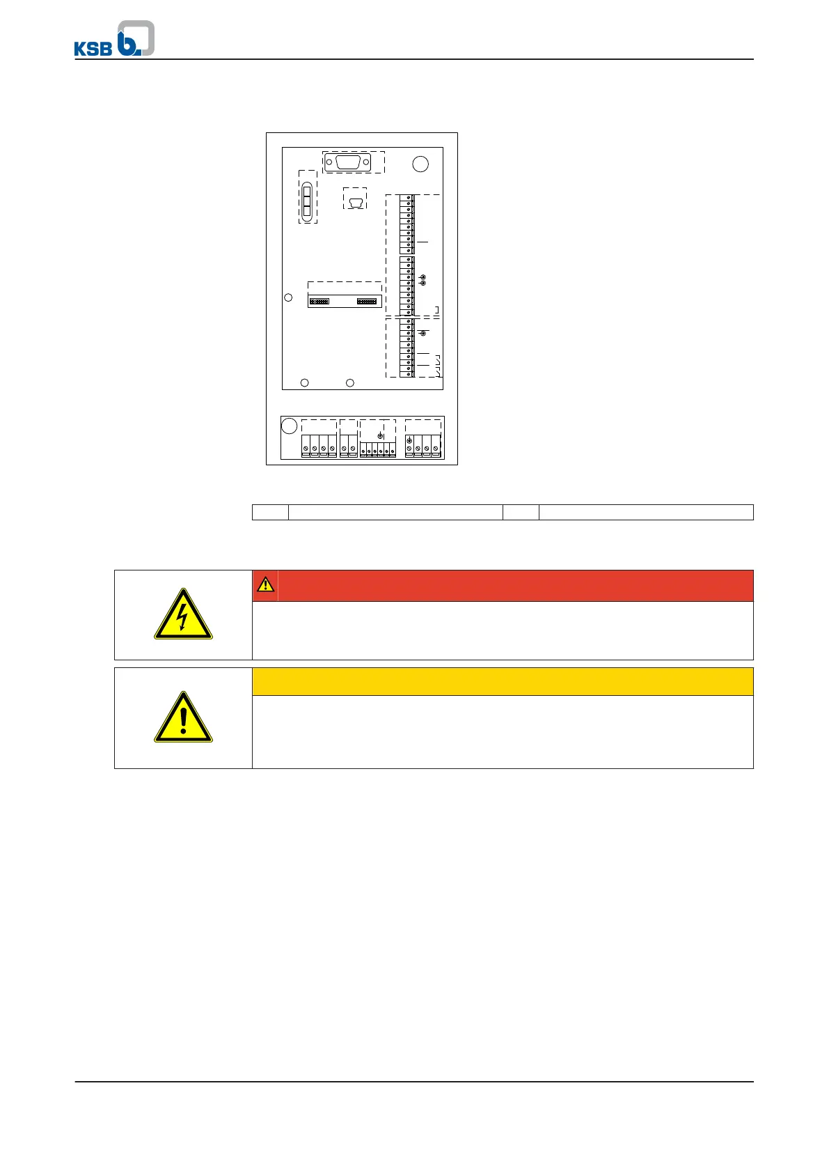
5.4.3.2 Overview of terminal strips
I
N
2
+
2
4V
31 2 4 5
PE L1 L2 L3 U V W
0
6
1
GND P4
DI6
DI5
DI4
DI3
DI2
DI1
+24V
AGND
AN-OUT
1
0
987654321 2019181716
1
5
141312
1
1
S B1_GND
S B1+
S B1-
S B1_GND
S B1+
S B1-
S B1Z-
S B1Z+
AGND P7
AIN1
GND
AIN2
+24V
NO2
COM2
NO1
COM1
10931
2
4 5 6
7
8
2
Fig. 8: Overview of terminal strips
1 Mains and motor connection 2 Control cables
5.4.3.3 Connecting mains and motor
DANGER
Touching or removing the terminals and connectors of the braking resistor
Risk of fatal injury due to electric shock!
▷ Never open or touch the terminals and connectors of the braking resistor.
CAUTION
Incorrect electrical installation
Damage to PumpDrive!
▷ Never fit a contactor (in the motor connection cable) between the motor and
PumpDrive.
1. Route the mains or motor connection cables through the cable glands and
connect to the specified terminals.
2.
Connect the line for a PTC connection/PTC thermistor to terminal strips 5/6.
If the sensor signal is transmitted to PumpDrive from a higher-level control
system or a PLC, make sure that all the signals are electrically isolated.
The motor temperature sensor connections must be implemented in accordance with
the IEC 664 standard.
The following measures must be complied with in the process:
▪ Live parts of the motor and sensor must have double or reinforced insulation.
▪ The reinforced insulation includes a leakage distance and clearance of 8 mm for
400/500 V AC devices.
If the connection cannot be effected as specified, proceed as follows:
▪ Method 1:
–
All other terminals for inputs and outputs must be protected so as not to
pose a shock hazard.
Connection in compliance
with standards
Optional connection
5 Installation at Site
26 of 162
PumpDrive