P7 terminal strip, terminals 1 to 4:
▪ The function of the two volt-free relays (NO) can be parameterised via the
control panel.
P7 terminal strip, terminals 5 to 10:
▪ Analog signals from a higher-level control station must be electrically isolated
when they are transmitted to PumpDrive, for example by using isolating
amplifiers.
▪ If an external voltage or current source is used for the analog inputs, the ground
of the setpoint or sensor sources is applied to terminal P7:10.
▪ The +24 V DC voltage source (terminals P7:5 and P7:7) is used as the power
supply for the actual value sensor if PumpDrive is in closed-loop control mode.
▪ Alternatively, analog input 2 can be connected to the mains/motor/PTC terminal
strip. In this case, do not assign the input on terminal strip P7:6.
5.4.3.7 Connecting the control panel
DANGER
Improper handling
Damage to PumpDrive!
▷ Only connect or remove the control panel when it is de-energised.
CAUTION
Electrostatic charging
Damage to the electronics!
▷ Before starting work on the control panel, personnel must ensure that they are
free of electrostatic charges.
▷ Only connect or remove the control panel when it is de-energised.
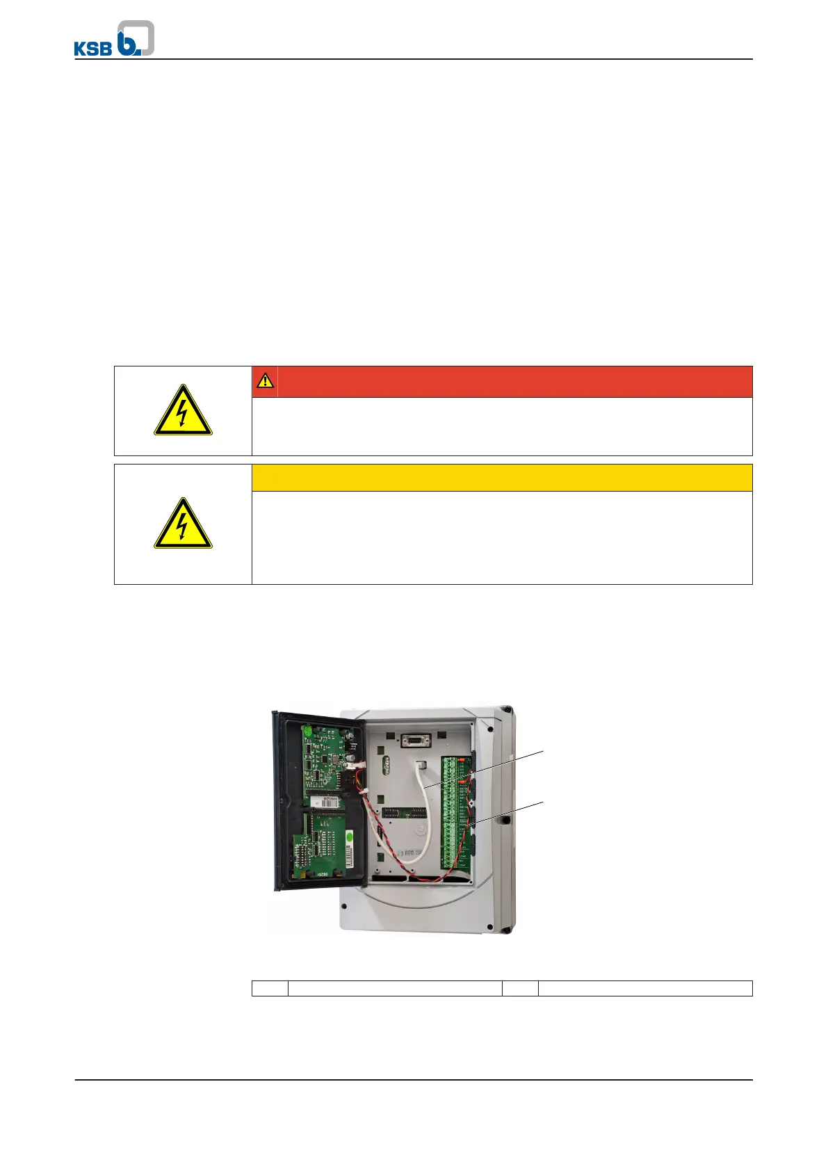
Mounting the standard control panel
✓ The following connections are available: 24 V, GND
1.
Undo the screws of the mounted blanking plate/control panel and remove the
blanking plate/control panel.
Fig. 18: Connecting cable ends
1 Mini USB connection 2 Supply voltage
2. Connect the red line (24 V) to terminal strip P4 (terminal P4:13) of PumpDrive.
3. Connect the black line (GND) to terminal strip P4 (terminal P4:20) of PumpDrive.
Relay outputs
Analog inputs
5 Installation at Site
34 of 162
PumpDrive