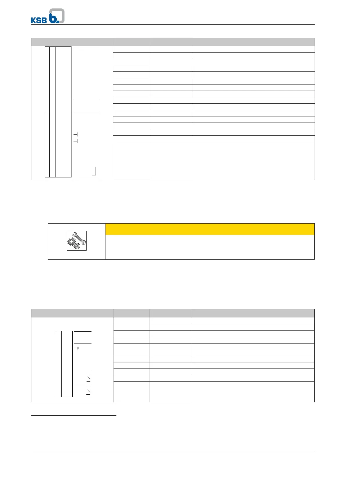
Terminal strip Terminal Signal Description
GND P4
DI1
DI2
DI3
DI4
DI5
DI6
DI1
+24V
AGND
AN OUT
SB1--GND
SB1+
SB1--
SB1--GND
SB1+
SB1--
SB1Z--
SB1Z+
20
19
18
17
16
15
14
13
12
11
10
9
8
7
6
5
4
3
2
1
16 DIG-IN3 Digital input (15/28 V DC)
15 DIG-IN2 Digital input (15/28 V DC)
14 DIG-IN1 Digital input (15/28 V DC)
13 +24 V +24 V DC voltage source, max. load 200 mA
12 0V-AN Ground for AN-OUT
11 AN OUT Analog output 0 - 10 V, max. load 5 mA
10 SB1-GND Ground for KSB local bus
9 SB1 + KSB local bus signal
8 SB1 - KSB local bus signal
7 PE (EARTH) Earth
6 PE (EARTH) Earth
5 SB1-GND Ground for KSB local bus
4 SB1 + KSB local bus signal
3 SB1 - KSB local bus signal
2 SB1Z- Bus terminator for KSB local bus
1 SB1Z+ Bus terminator for KSB local bus
Terminal strip P4, terminals 13 to 20:
▪ PumpDrive is equipped with 6 digital inputs. Digital inputs 1 and 6 are factory-
defaulted.
▪ The functions of digital inputs 2 to 5 can be parameterised as required.
▪ Use terminal P4:13 (+24 V DC) to connect the inputs.
CAUTION
Differences in potential
Damage to PumpDrive!
▷ Never connect an external +24 V DC voltage source to a digital input.
Terminal strip P4, terminals 11 and 12:
▪ PumpDrive is equipped with an analog output whose output value can be
parameterised via the control panel.
▪ Analog signals to a higher-level control station must be electrically isolated when
they are transmitted, for example by using isolating amplifiers.
Table 20: Control terminal assignment, P7 terminal strip
Terminal strip Terminal Signal Description
AIN1
AGND P7
GND
AIN2
NO2
COM2
NO1
COM1
+24V
10
9
8
7
6
5
4
3
2
1
10 0V-AN
Ground for AIN 1/2
31)
9 AN1-IN
Programmable analog input 1
32)
8 PE (EARTH) Earth
7 0V Ground for +24 V
6 AN2-IN Programmable analog input 2, factory setting:
Actual value source 4 - 20 mA
5 +24 V +24 V DC voltage source, max. load 200 mA
4 NO2 NO contact, "NO" No. 2 (250 V AC, 1 A)
3 COM2 NO contact, "NO" No. 2 (250 V AC, 1 A)
2 NO1 NO contact, "NO" No. 1 (250 V AC, 1 A)
1 COM1 NO contact, "COM" No. 1 (250 V AC, 1 A)
Digital inputs
Analog outputs
31)
The ground at terminal P7:7 can also be used to connect an analog ground. AGND and GNG have the same potential.
32)
Analog signals from a higher-level control station must be electrically isolated when they are transmitted to PumpDrive,
for example by using isolating amplifiers.
5 Installation at Site
PumpDrive
33 of 162