Table 18: Cable cross-sections of control terminals
Control terminal Core cross-section Maximum cable diameter
[mm]
Rigid and flexible cores
[mm
2
]
Flexible cores with wire end
sleeves
[mm
2
]
P4 terminal strip 0,2-1,5 0,75
9,5
30)
P7 terminal strip 0,2-2,5 0,25-1,5
GN D P 4
DI6
DI5
DI4
DI3
DI2
DI1
+24V
AGND
AN-OUT
1098765432
1 2019181716151413
12
11
SB1_GND
SB1 +
SB1 -
SB1_GND
SB1 +
SB1 -
SB1 Z-
SB1 Z+
ABNG P7
AIN1
GND
AIN2
+24V
NO2
COM2
NO1
COM1
10
9
31
2 4 5 6 7 8
P4
P7
P8
P5
P9
P6
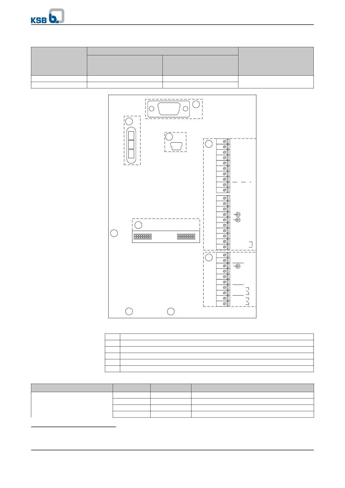
Fig. 17: Control terminals
P4 P4 terminal strip
P5 Service interface: RS232
P6 LED traffic light function
P7 P7 terminal strip
P8 Field bus module connection panel
P9 Display connection
Table 19: Control terminal assignment, P4 terminal strip
Terminal strip Terminal Signal Description
20 0V Ground for +24 V
19 DIG IN6 Digital input (15/28 V DC)
18 DIB-IN5 Digital input (15/28 V DC)
17 DIG-IN4 Digital input (15/28 V DC)
30)
Impairment of protection provided by enclosure when cable diameters other than those specified are used.
5 Installation at Site
32 of 162
PumpDrive